

When a PV string needs overcurrent protection
Assess whether string overcurrent protection is required from the array topology, potential reverse-fault contributions, module instructions, conductor limits and applicable installation rules. A label such as combiner or bifacial does not establish that every string needs a fuse.
When protection is required, identify the protected circuit and the specified PV DC protective device. Separate its fault-clearing role from any switching, isolation or current-monitoring function.
Design current and the applicable calculation method
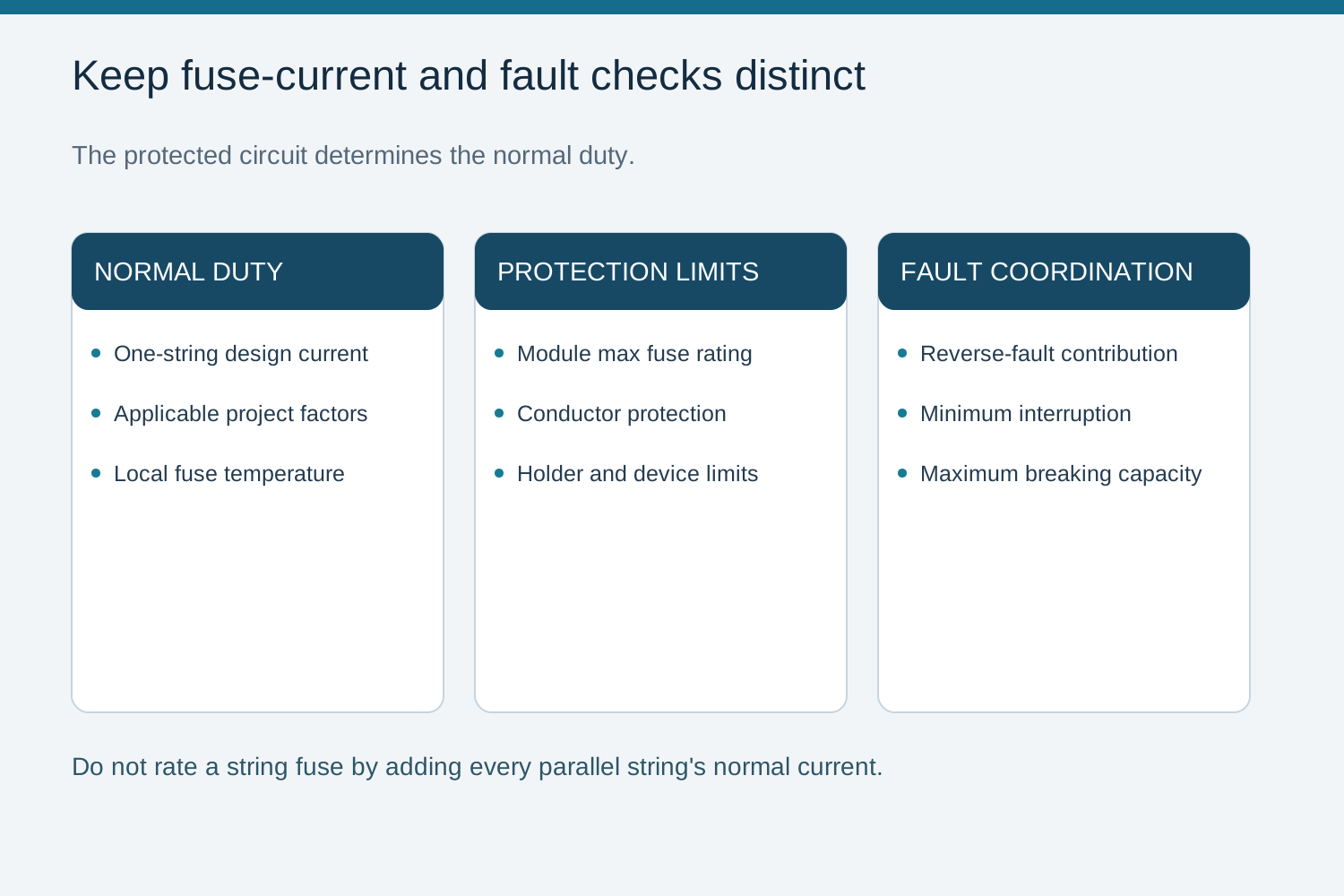
First identify whether the fuse protects one PV string or a combined output circuit. A string fuse carries its own string current in normal operation; an output fuse carries the combined current of its connected strings. The installation rules and equipment instructions establish the calculation method for each circuit. Record the region and edition before applying any current factor.
Collect module Isc, maximum series fuse rating, string count, maximum system voltage, cable ratings and the expected temperature around the fuse. Include bifacial or irradiance allowances required by the project.
Use the governing design method and equipment instructions to establish the normal design current, including required irradiance and bifacial allowances. IEC 60269-6 is a fuse product standard; it does not make one numerical multiplier a complete installation selection rule.
3. Worked example
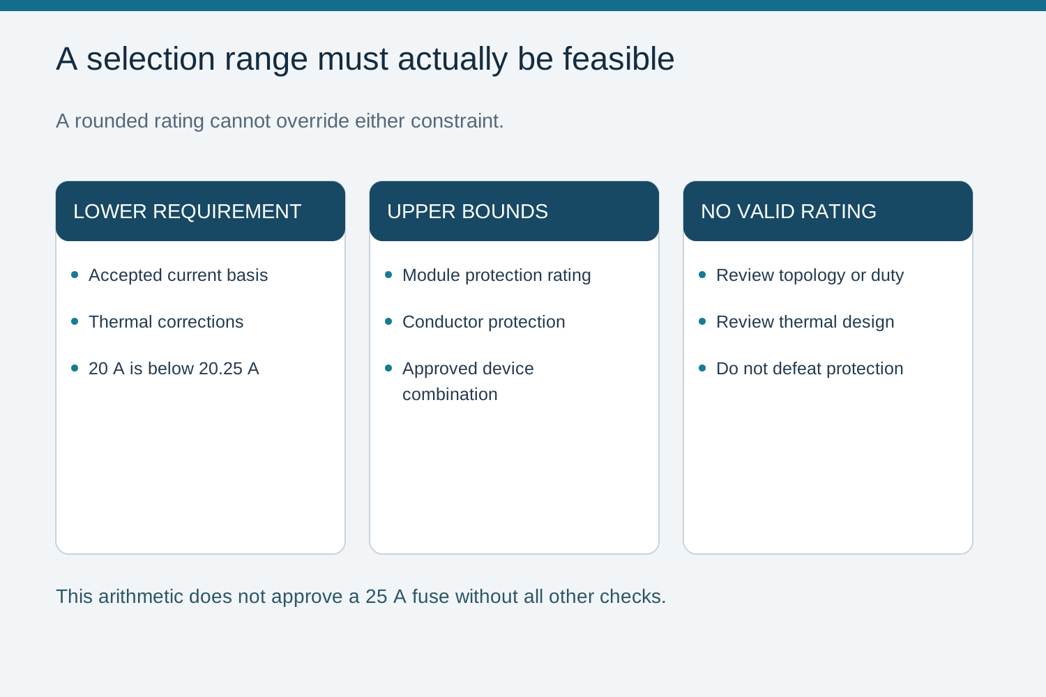
An arithmetic lower-bound example illustrates a rounding error: if an accepted project calculation gives 20.25 A as the required minimum rated current, 20 A is below that minimum. The calculation does not approve a 25 A fuse either: module, conductor, holder, temperature and fault-coordination limits still need to allow the selected rating.
If no available fuse satisfies both the current-carrying requirement and the protection upper bounds, review the configuration or thermal design. Do not round down the minimum or exceed the permitted protection rating simply to fit a catalogue size.
4. Reverse current between parallel strings
The module maximum series fuse rating is the maximum overcurrent-protective fuse rating permitted by the module manufacturer. It is not the current that the module can carry continuously in reverse, and it is not a fuse melting threshold. Select the string fuse rated current to carry the required normal design current while staying within the module and conductor protection limits.
Next calculate the reverse-fault current that parallel strings or other connected supplies could deliver through the faulted string. Compare that current with the fuse time-current characteristic, minimum interruption capability, maximum breaking capacity and the protected circuit damage limits. Do not select a string fuse rated current by adding all parallel-string currents: that sum belongs in the fault assessment, or in normal-current sizing for an actual combined output circuit.
5. Fuse class matters
Specify a fuse approved for the PV DC duty with the required voltage, interruption range and time-current behavior. Confirm the holder and assembly combination as well as the fuse-link. A nominal ampere value is insufficient evidence for DC fault clearing.
Use the exact device data to assess low-magnitude fault interruption and maximum breaking capacity. A claimed fuse class or a generic AC fuse label does not establish those capabilities for the proposed circuit.
6. Coordination with the rest of the box
Check the fuse-link and holder separately at the expected local temperature. Manufacturer ambient, enclosure and cycling corrections can reduce the usable continuous current of the selected combination. A holder current rating does not eliminate the need to check the fuse-link curve and permissible power dissipation. Excess temperature can cause unwanted opening or damage even where the nameplate current appears adequate.
If the required continuous-current margin cannot fit below the module or conductor protection limit, change the equipment arrangement or thermal design. Do not simply increase the fuse rating beyond the permitted maximum. Check the completed combination against the assembly temperature-rise evidence and installation conditions.
Send NEUTRON the string-circuit schedule, module maximum series fuse rating, design current, maximum cold voltage, expected enclosure temperature and the selected fuse-link and holder requirements. For standard DC combiner configuration discussions, also identify the fault-current coordination basis and cable termination sizes. This keeps the requested enclosure and protection arrangement tied to the project design rather than to an isolated ampere value.
Qualified personnel must assess the actual configuration and isolation boundary. Verify equipment ratings, manufacturer instructions and the governing design procedure before selection or testing.
Frequently asked questions
Should a string fuse be rated for all parallel strings?
No. Its normal current rating is selected for the protected string under the applicable design method. The current from other parallel strings is evaluated separately as a possible reverse-fault contribution and checked against interruption and protection performance.
What sets the fuse upper bound?
The selected fuse rating must not exceed the module manufacturer maximum series fuse rating and must also protect the conductor. That module value is not a continuous reverse-current limit or an instantaneous fuse-opening threshold.
Does heat change the fuse size?
Yes. Verify fuse-link and holder performance at the expected local temperature using their respective manufacturer data. If adequate continuous-current capability conflicts with a protection limit, redesign the arrangement rather than exceed the limit.
What must be checked after choosing the current rating?
Verify maximum cold system voltage, minimum and maximum fault-current interruption, clearing time against circuit withstand, holder compatibility and thermal conditions. The final choice requires more than an Isc multiplier.
Bring the design and verification records to the review.
Send NEUTRON the string-circuit schedule, module maximum series fuse rating, design current, maximum cold voltage, expected enclosure temperature and the selected fuse-link and holder requirements. For standard DC combiner configuration discussions, also identify the fault-current coordination basis and cable termination sizes. This keeps the requested enclosure and protection arrangement tied to the project design rather than to an isolated ampere value.
Discuss a projectContinue learning
Explore related technical guidance in Solar PV.
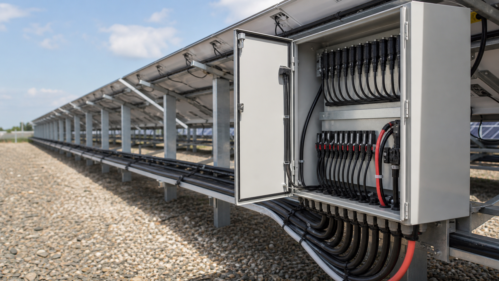

Engineering guidance: use the actual equipment instructions, applicable installation rules and project-specific evidence. Generated imagery is not evidence of an installed NEUTRON product.