
1. The voltage-drop formula
For a two-wire DC circuit with similar outgoing and return conductors, the loop voltage drop is ΔV = 2 × L × I × r(T), when L is the one-way length and r(T) is resistance per unit length. Keep the units consistent. For unequal paths or conductors, calculate each part of the loop separately.
State the operating voltage used for the percentage and distinguish operating current for energy loss from the current basis used for conductor protection. A voltage-drop calculation alone does not approve a cable installation.
2. Why temperature belongs in the calculation
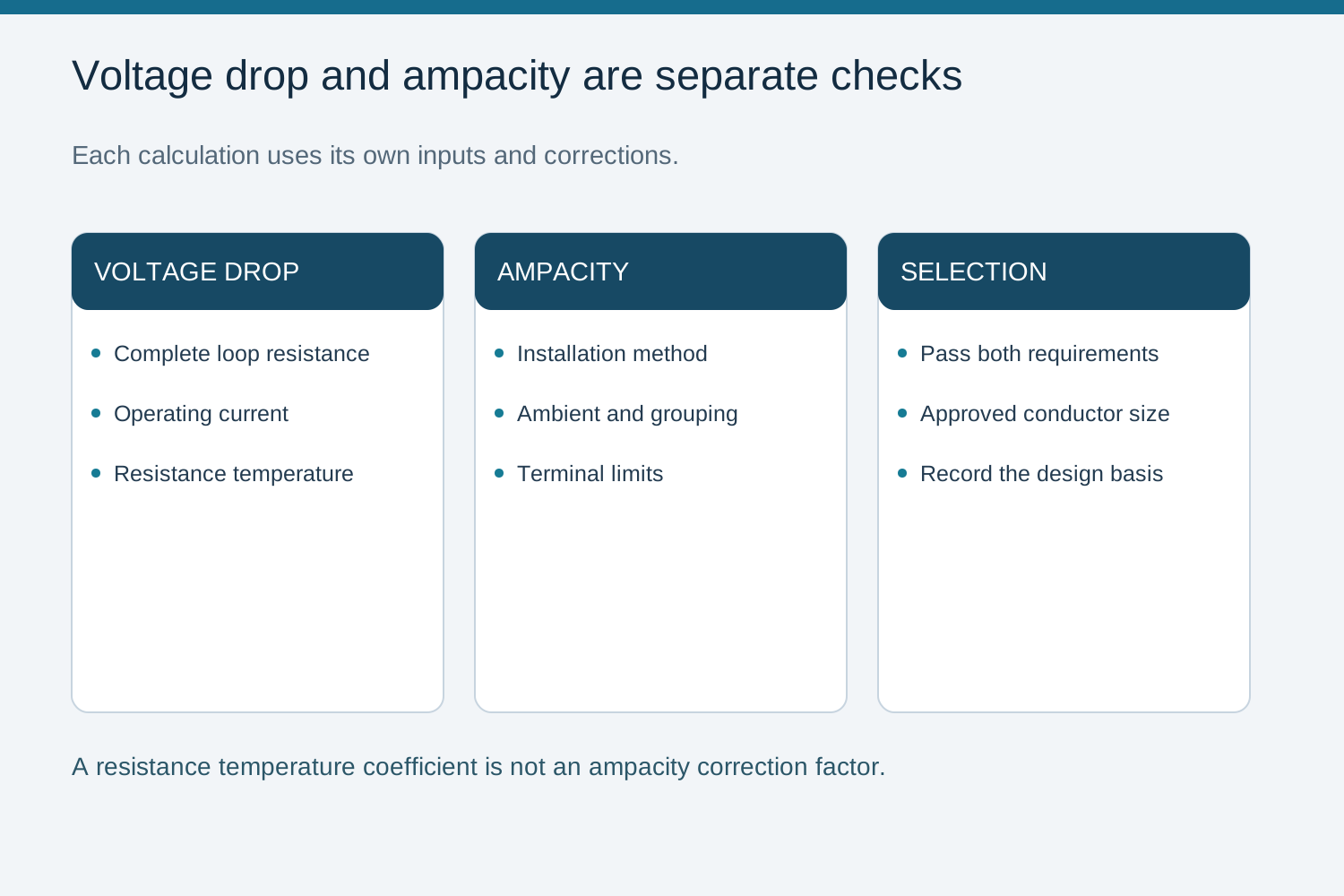
For voltage drop, adjust conductor resistance from its reference temperature using the material resistance coefficient, for example R(T) = R20 × [1 + α20 × (T − 20 °C)] where that model is applicable. For ampacity, use the separate correction factors for ambient temperature, grouping and installation method from the applicable cable data or standard. The resistance coefficient is not an ampacity multiplier. Select a cross-section that meets both checks and remains compatible with the terminals.
3. Worked example
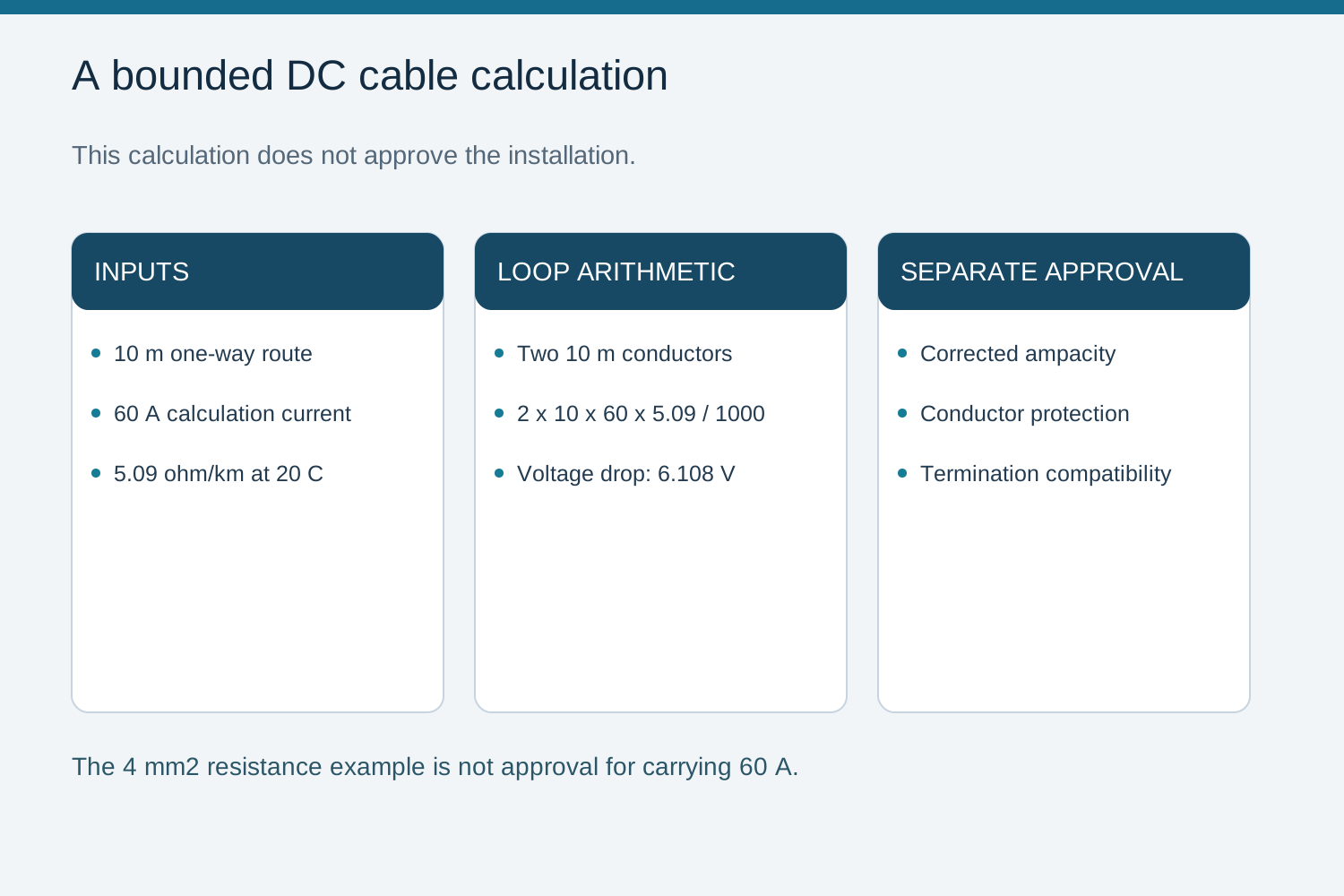
Consider a two-wire DC circuit with a one-way route length of 10 m, current of 60 A and 4 mm² copper cable resistance of 5.09 ohm/km at 20 °C, as listed for LAPP ÖLFLEX SOLAR H1 BUR. The loop voltage drop is ΔV = 2 × 10 × 60 × 5.09 / 1000 = 6.108 V. This arithmetic example does not approve 4 mm² cable for a 60 A installation: ampacity and termination checks may require a larger size. Use the operating voltage to express the drop as a percentage.
For this example, 2 × 10 × 60 × 5.09 / 1000 = 6.108 V. The two 10 m conductors form the return loop. Retain the source resistance and temperature with the calculation; do not convert the example into a recommendation for a 60 A, 4 mm² installation.
4. The two checks that must both pass
Determine corrected ampacity from the applicable cable data, installation method, ambient temperature and grouping. Separately calculate voltage drop at the relevant conductor temperature. The selected conductor must satisfy both requirements and fit the approved terminals.
If either check fails, review the cross-section and installation design. A universal current multiplier or voltage-drop percentage cannot establish compliance for every jurisdiction and circuit.
5. Ampacity and installation method
Start with the circuit design current and maximum voltage, then record conductor material, insulation rating, route length, installation method, ambient temperature, grouping and terminal limits. For the output circuit, use the combined current of the connected strings with the factors required by the applicable design method. These inputs establish the cable or busbar selection basis.
Use documented correction factors for the particular cable and installation. Avoid transferring a percentage reduction from another route, insulation material or ambient condition. Keep the data revision and assumptions in the cable schedule.
6. When thicker is not better
Compare alternative sizes through corrected ampacity, voltage drop, termination compatibility and the project loss budget. Additional copper is one option; route and system-design changes need their own engineering review. Raising string voltage is constrained by cold-condition voltage and every equipment input limit.
There is no universally safe voltage-drop percentage independent of ampacity and protection. Estimate annual energy consequences with an operating profile rather than inferring them from one peak-load point.
Cable and busbar resistance share a formula, not a rating table
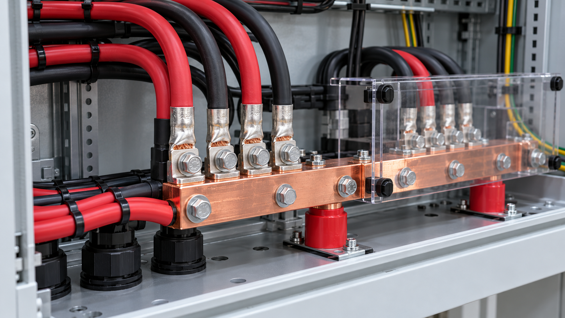
The relation ΔV = I × R applies to both cables and busbars. A busbar needs resistance data for its material, geometry and temperature, plus assessment of connections; its thermal rating also depends on surface cooling, enclosure layout and support arrangement. Do not transfer cable ampacity tables to a busbar. Verify the bar and its joints within the assembled equipment.
Record design current, material, installation method, temperature and terminal limits.
Use the same electrical resistance principles but the appropriate thermal model for each conductor form.
Select using the actual conductor and assembly data rather than the example dimensions.
Qualified personnel must assess the actual configuration and isolation boundary. Verify equipment ratings, manufacturer instructions and the governing design procedure before selection or testing.
Frequently asked questions
What basis must conductor sizing state?
Record design current, maximum voltage, material, insulation, route length, installation method, ambient temperature, grouping and terminal limits. Output circuits use the aggregate string current with the factors required by the applicable design method.
Does the voltage-drop equation also apply to a busbar?
Yes. Voltage drop is current multiplied by resistance, but use resistance for the actual bar geometry, material, temperature and joints. Determine busbar ampacity separately from its thermal design and assembly verification.
How do I pick the governing limit?
Choose a cross-section meeting both the corrected ampacity requirement and the voltage-drop budget. If the two checks give minimum cross-sections, select the larger requirement; also check terminal and installation compatibility.
Which cable resistance should I use?
Use resistance for the actual cable and operating temperature. The 4 mm² value of 5.09 ohm/km at 20 °C illustrates the calculation only. Apply separate ampacity correction factors; do not reuse the resistance temperature coefficient as a current-rating correction.
Bring the design and verification records to the review.
Customers can provide NEUTRON LLC with the single-line diagram, string and output currents, maximum DC voltage, conductor sizes, routing conditions and termination requirements for a combiner configuration enquiry. These inputs help define the requested connection arrangement without treating a general example as a project cable schedule.
Discuss a projectContinue learning
Explore related technical guidance in Solar PV.



Engineering guidance: use the actual equipment instructions, applicable installation rules and project-specific evidence. Generated imagery is not evidence of an installed NEUTRON product.