
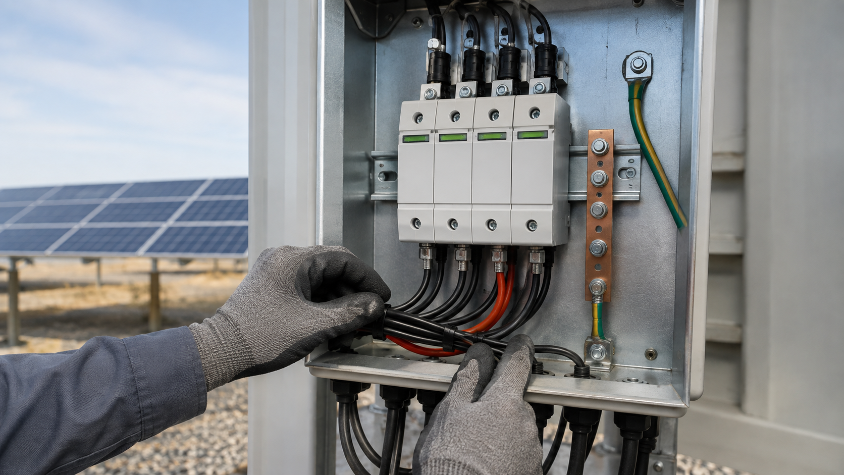
Why the SPD belongs in the combiner
The combiner is the first enclosed stage after the field wiring, so it is the natural place to interrupt a surge. A correctly fitted SPD protects the 1000 V or 1500 V DC bus and every string fuse feeding it, and it reduces the chance of melted terminals and extended downtime.
- Protects the DC bus from lightning-induced overvoltage on long array cables.
- Reduces equipment damage that would otherwise force a site outage.
- Forms part of the insulation coordination strategy for the whole DC chain.
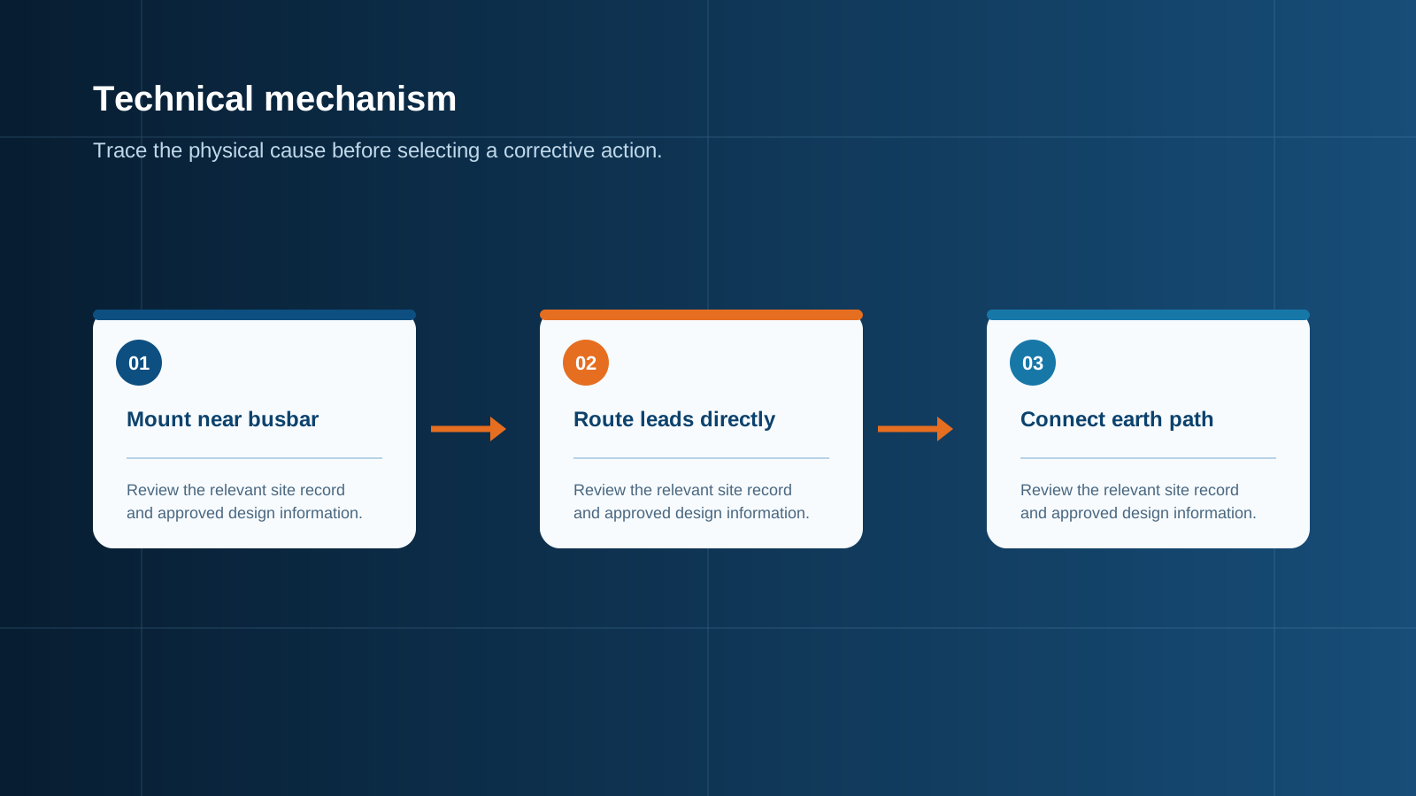
Technical diagram shown at a readable responsive scale.
Type 1 versus Type 2 (IEC 61643-31)
IEC 61643-31 classifies SPDs for photovoltaic applications. Type 1 devices withstand a direct lightning current with a 10/350 microsecond waveform and are specified where an external lightning protection system is present. Type 2 devices handle induced surges with an 8/20 microsecond waveform and suit most combiner boxes without a direct-strike threat. Combined Type 1+2 devices are common at the combiner where both threats may occur.
- Type 1: direct strike, 10/350 us, used with an external LPS.
- Type 2: indirect surge, 8/20 us, general combiner protection.
- Combined Type 1+2: one device for mixed exposure sites.
Selecting Ucpv and Up
Ucpv is the maximum continuous operating voltage the SPD tolerates on the protected DC pole. It must exceed the array open-circuit voltage at the highest expected operating temperature, with margin for aging. The voltage protection level Up is the residual clamping voltage under surge current; it must stay below the impulse withstand of the connected equipment, namely the busbar insulation and the inverter DC input.
- Choose Ucpv above Voc,max with a temperature-derating margin.
- Keep Up below the equipment impulse withstand voltage.
- Match the SPD pole arrangement to the array (positive, negative, or both rails).
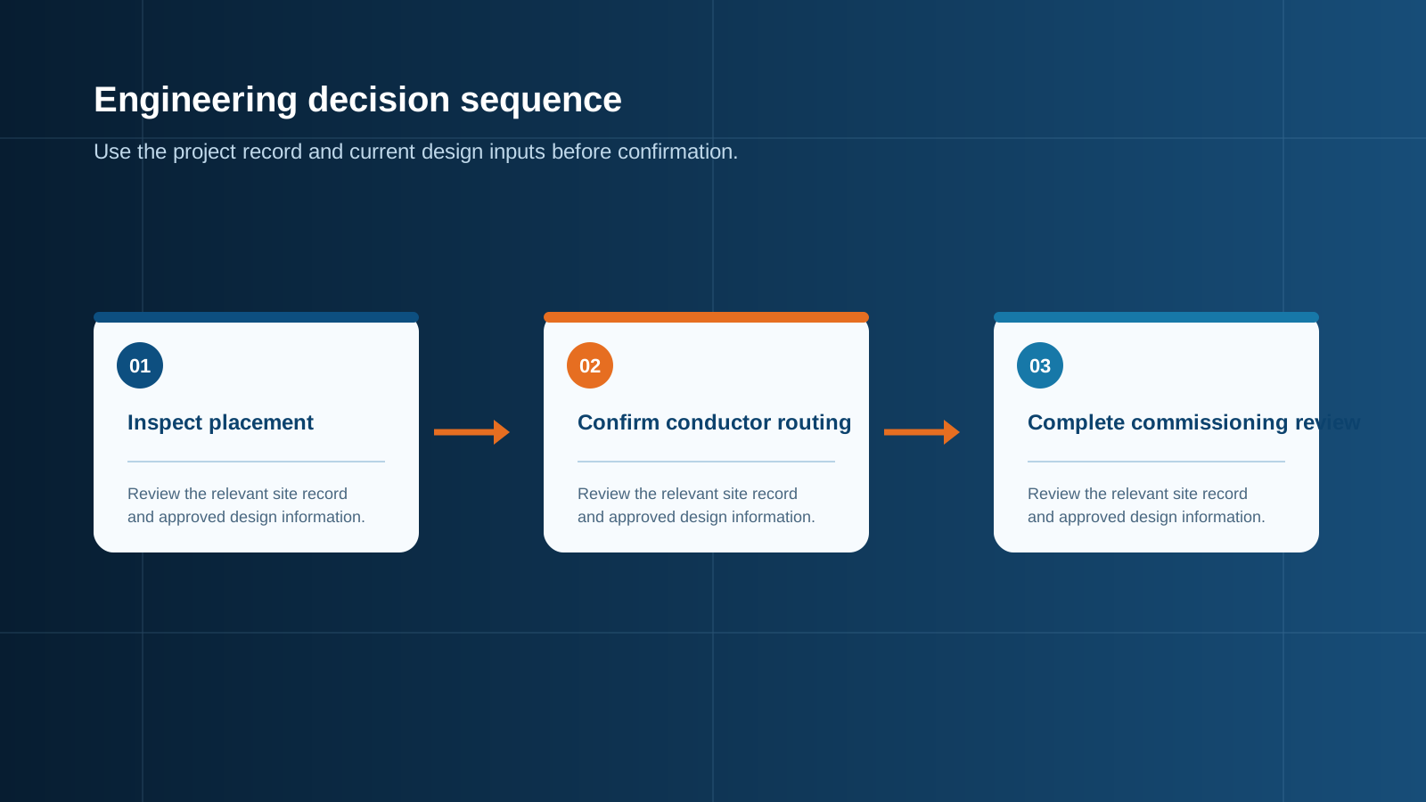
Technical diagram shown at a readable responsive scale.
Y-configuration wiring
In a Y (star) configured SPD the protection elements connect from each DC rail to a common midpoint that is bonded to earth. This arrangement protects both the positive and negative conductors relative to ground with a single coordinated set, which suits bipolar PV arrays. The midpoint must be solidly earthed through the bonding conductor so the clamping path is effective.
- One star point bonded to the protective earth reference.
- Protects both rails against ground-referenced transients.
- Simpler wiring than discrete rail-to-rail devices.
The 50 cm lead-length rule
The conductors between the SPD and the busbar must be kept short. A widely applied rule limits the total lead length, counting both the pole conductor and the protective-earth return, to about 50 cm. Longer leads add inductance that raises the effective clamping voltage at the equipment during a fast surge, partially defeating the SPD. Place the device next to the busbar and route the earth lead directly to the bonding bar.
- Keep the total lead length, both conductors, near 50 cm maximum.
- Shorter is better; mount the SPD beside the busbar.
- Avoid loops and long detours to earth.
Grounding the SPD
The SPD earth lead must connect to the combiner box equipotential bonding bar with the shortest practical conductor. A long or thin earth lead increases impedance and weakens protection. The bonding bar then ties to the enclosure, the cable armour and the array frame reference so the whole assembly shares one earth potential.
- Connect to the local bonding bar, not a distant point.
- Use a low-impedance, adequately sized conductor.
- Verify continuity to the enclosure and frame.
Status indication
Modern combiner SPDs include a thermal disconnector and a status indicator, either a green or red window or a remote alarm contact. The indicator shows whether the device is healthy or has reached end of life after absorbing surges. Wiring the alarm contact to the monitoring unit lets operators see degradation without opening the enclosure.
- Visual window: green means healthy, red means fault.
- Remote alarm contact for central monitoring.
- Replace the module at end of life instead of bypassing it.
Commissioning
After installation the SPD must be verified before the array is energized. Confirm the type, Ucpv and Up match the design, check the lead length, and measure the bonding resistance. A commissioning record stating these values supports later maintenance and warranty discussions.
- Verify type, Ucpv and Up against the specification.
- Measure bonding resistance to the earth bar.
- Record serial numbers and test results.
This is general technical guidance. Confirm final ratings, protection coordination, installation and applicable local requirements against current standards, manufacturer documentation and the approved project design.
Frequently asked questions
What is the difference between Type 1 and Type 2 SPDs for a combiner box?
Type 1 withstands direct lightning current (10/350 us) and suits sites with an external lightning protection system. Type 2 handles induced surges (8/20 us) and fits general combiner protection. Combined Type 1+2 devices cover both.
What does Ucpv mean for a PV surge protective device?
Ucpv is the maximum continuous operating voltage the SPD tolerates on the DC pole. It must exceed the array open-circuit voltage at the highest operating temperature with margin so the device does not age prematurely.
Why must the SPD lead length be kept short in a combiner box?
Every extra centimetre of lead adds inductance that raises the effective clamping voltage during a fast surge. Keeping the total lead near 50 cm preserves the protection level at the busbar.
What is Y-configuration SPD wiring?
In a Y configuration the SPD elements connect from each DC rail to a common midpoint bonded to earth, protecting both rails against ground-referenced transients with one coordinated set.
How do you commission a combiner box SPD?
Verify the type, Ucpv and Up against the design, confirm the lead length, measure the bonding resistance to the earth bar, then record serial numbers and test results before energizing.
Discuss your PV combiner requirement
Share the system voltage, string count, inverter interface and installation environment. NEUTRON can review the equipment configuration around your project documentation.
Discuss a projectContinue learning
Explore related technical guidance in Electrical Protection.

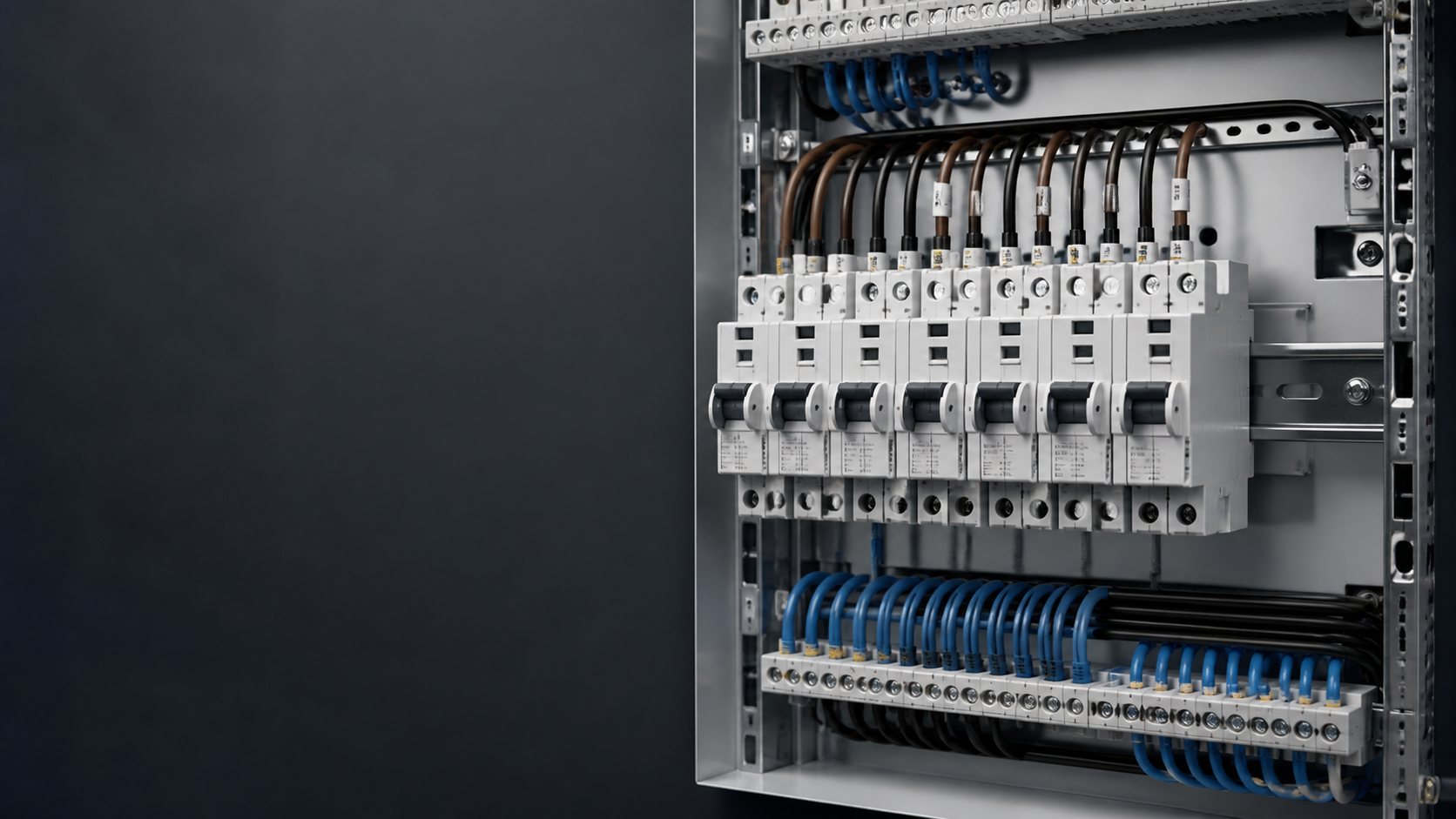
Published from the approved Period 09 source package. Technical values and final design decisions must be verified against the current applicable standard, manufacturer documentation and approved project design.