
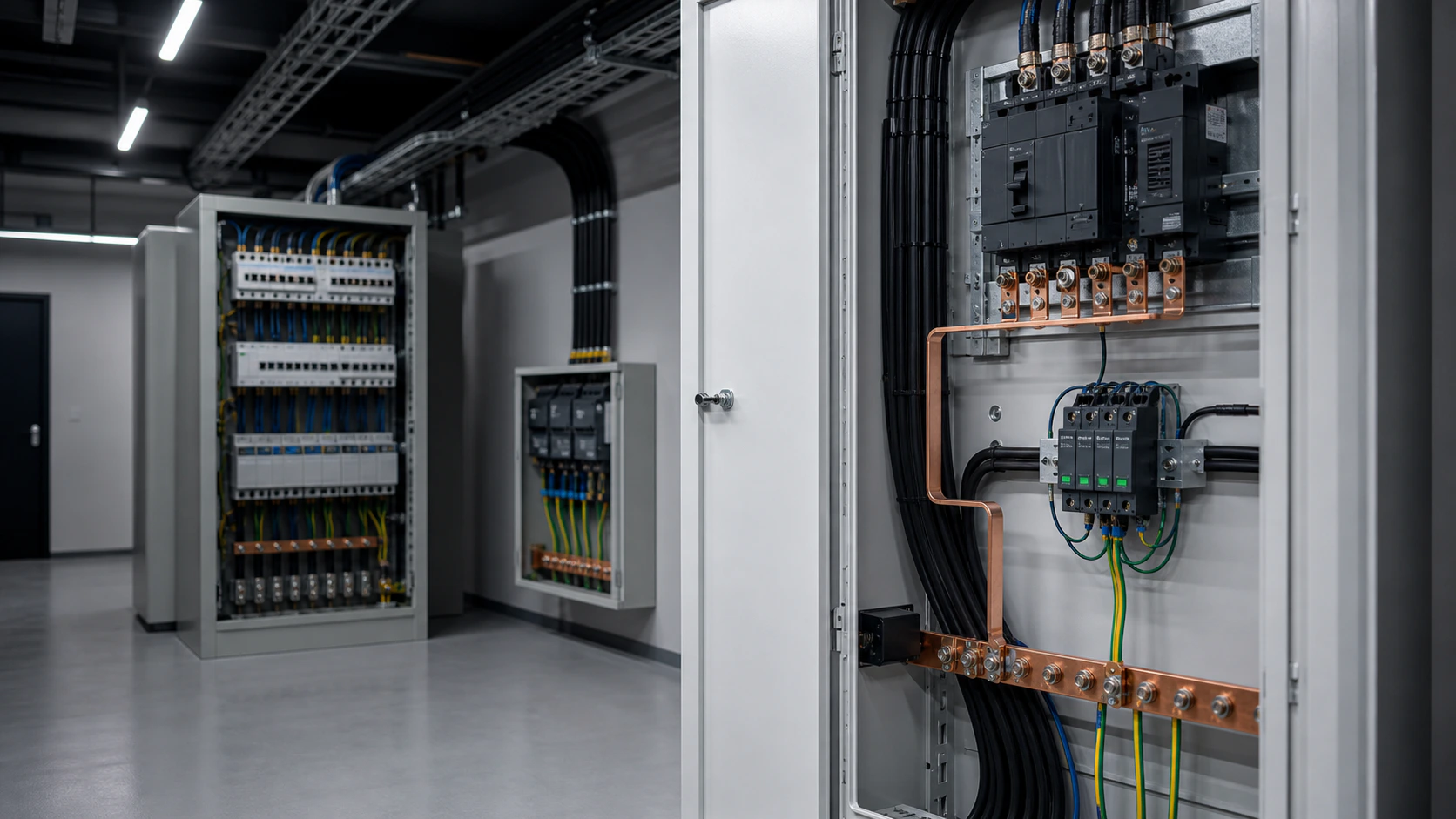
2. Type 1 (Class I): service entrance protection
Type 1 devices are tested with the 10/350 µs impulse current waveform, which represents the energy content of a partial direct lightning current. The headline parameter is Iimp, quoted in kA per pole, typically 12.5 kA to 25 kA.
Install a Type 1 device where a direct strike can inject current into the installation: buildings fitted with an external lightning protection system, structures on exposed ground, overhead line service entries, telecom masts and photovoltaic arrays on tall buildings. It goes at the main incoming panel, as close to the origin of the installation as the earthing arrangement allows.
A Type 1 device on its own is rarely enough. Its let-through voltage Up is relatively high — typically 1.5 kV to 2.5 kV — because it is engineered to survive enormous energy rather than to clamp tightly. Downstream equipment still needs a Type 2 stage to bring Up down to a level the electronics can tolerate.
8. Installation mistakes that neutralise a correct selection
- Long connecting leads. Every metre of conductor adds roughly 1 kV of inductive voltage drop during an 8/20 µs surge. Keep the combined length of the phase and earthing conductors to 50 cm or less; use the V-connection method where that is impossible.
- Undersized earthing conductor. Use a two-colour conductor of at least 4 mm², sized up in line with the module rating.
- Missing backup protection. Fit the specified upstream fuse — a 32 A device is typical for mid-range modules — so a failed varistor cannot hold a fault on the board.
- Wrong wiring method for the load current. Below 100 A the supply can pass through the device terminals; above 100 A, tee the device off the busbar so the conductor size is independent of load current.
- Skipping the N-PE module in a TT system, which leaves the neutral-to-earth path unprotected.
- Never inspecting the indicators. A red window means the module has already done its job and the board is now unprotected.
1. What a surge protective device actually does
A surge protective device sits in parallel with the circuit, not in series. Under normal conditions it is effectively an open circuit in a high-resistance state. When a transient overvoltage appears — from a lightning strike, a switching operation, a capacitor bank energising or a fault clearance — the varistor or spark gap inside conducts within nanoseconds and diverts the surge current to earth. Once the transient has passed, the device returns to its high-resistance state and the supply continues uninterrupted.
Two standards govern the subject. IEC 61643-11 defines the product requirements and test classes. IEC 61643-12 defines selection and application, and it works together with the risk assessment in IEC 62305-2. For photovoltaic DC circuits, IEC 61643-31 applies instead.
The reason this is not optional: most electronic equipment in a modern building has a rated impulse withstand voltage of 1.5 kV or 2.5 kV, while an unprotected 230/400 V installation can see transients of several kilovolts from a strike several hundred metres away. Insurance conditions and grid connection agreements increasingly make coordinated protection a contractual requirement.
3. Type 2 (Class II): distribution board protection
Type 2 devices are tested with the 8/20 µs waveform, which represents induced and switching surges rather than a direct strike. Two parameters matter: the nominal discharge current In, which the device must survive repeatedly, and the maximum discharge current Imax, which it must survive once.
This is the workhorse category. A Type 2 device belongs in every main distribution board, every sub-board more than 10 m of cable away from the previous stage, every photovoltaic combiner box, and every control panel feeding sensitive automation. In buildings without an external lightning protection system, a Type 2 device at the origin is often the complete solution.
Typical Type 2 ratings run from In 5 kA / Imax 10 kA for a small final board up to In 30 kA / Imax 60 kA for a main incomer on an exposed site. Voltage protection levels of 1.2 kV to 1.5 kV are normal.
4. Type 3 (Class III): terminal equipment protection
Type 3 devices are tested with a 1.2/50 µs open-circuit voltage and 8/20 µs short-circuit current combination wave, characterised by Uoc — commonly 6 kV or 10 kV. Their job is fine protection immediately in front of a specific load.
Use them for equipment that both matters and sits far from the board: medical imaging, laboratory instruments, building management controllers, IT racks, machine tool CNC panels. They are fitted in socket outlets, in the equipment enclosure, or on a short spur within a few metres of the load.
The hard rule is that a Type 3 device must never be the only protection. Its energy handling is small, and without a Type 2 upstream it will be destroyed by the first significant surge. Coordination between stages is what makes the chain work.
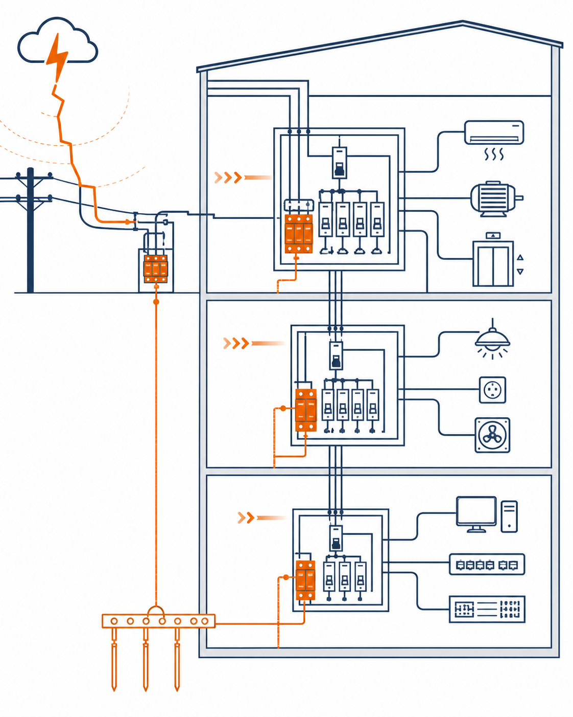
5. Technical comparison table
Table — Type 1, Type 2 and Type 3 SPDs to IEC 61643-11
6. Reading the datasheet: Uc, Up, In, Imax, Iimp
- Uc — maximum continuous operating voltage. It must exceed the highest steady-state voltage the device will see, including neutral displacement. For 230/400 V TN systems a Uc of 275 V or 320 V is common; TT and IT systems usually need 320 V, 385 V or higher.
- Up — voltage protection level. This is the number that protects your equipment. It must sit comfortably below the rated impulse withstand voltage of the load, with margin for the additional voltage drop across the connecting leads.
- In — nominal discharge current, 8/20 µs. The device must survive this repeatedly without degradation.
- Imax — maximum discharge current, 8/20 µs. A single-shot survival figure, not a design margin.
- Iimp — impulse current, 10/350 µs. Only quoted for Type 1 devices.
- Response time — how fast the varistor conducts. Values below 25 ns are typical for metal oxide varistor modules.
- Follow-current interrupt and short-circuit withstand — determines the backup fuse or circuit breaker you must fit upstream.
7. NEUTRON WCU8 modular surge protection range
NEUTRON manufactures the WCU8 series of modular surge protection devices for AC 50/60 Hz distribution circuits at 110 V, 230 V and 400 V. The design uses a DIN rail base with detachable plug-in modules, so a degraded module can be replaced individually without shutting down the board.
Table — NEUTRON WCU8 series — published ratings
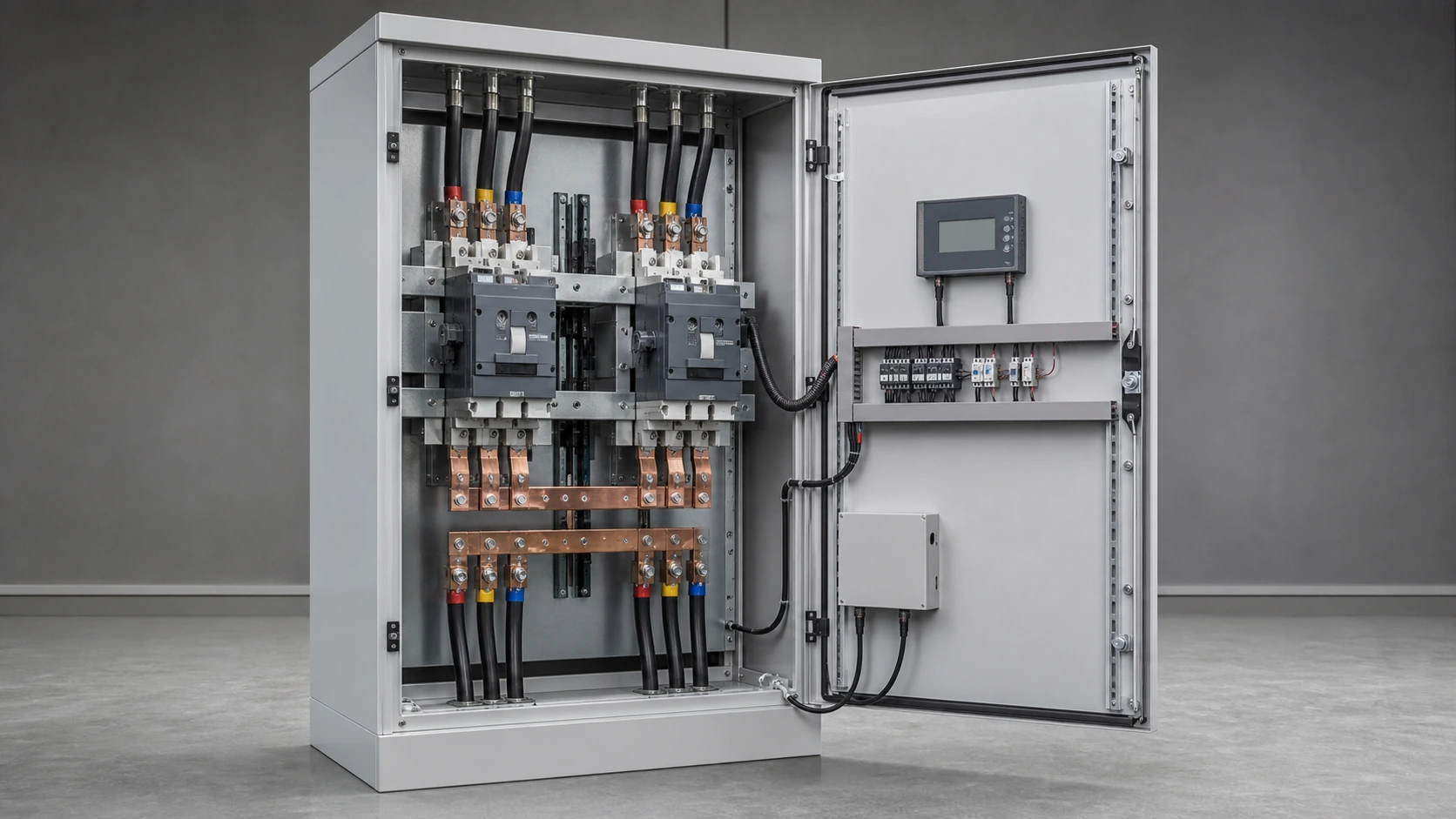
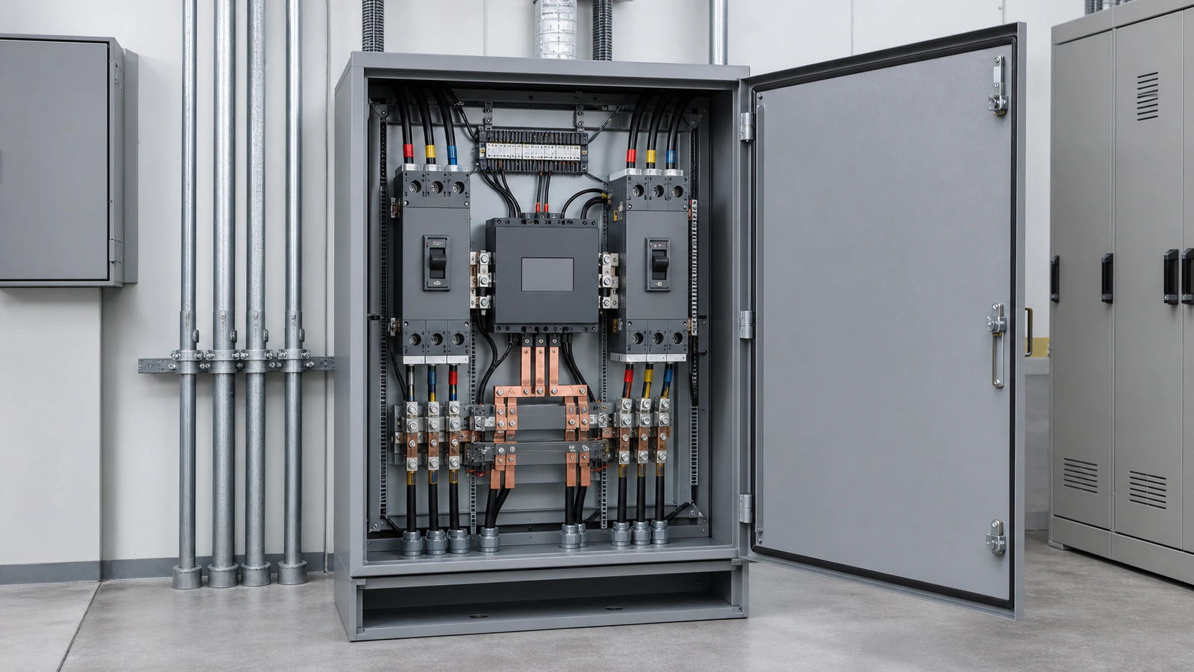
NEUTRON also integrates these modules into finished assemblies — GGD and GCS switchgear, XL-21 power distribution cabinets, photovoltaic combiner boxes and grid-connected cabinets — built and verified to IEC 61439-1 and IEC 61439-2 with CE and CB documentation.
- Response time below 25 ns and an operating range of −40 °C to +85 °C.
- Thermal disconnect device in every module: green indicator in service, red after disconnection, so a visual inspection is enough to confirm status.
- Optional remote signalling contact, normally open, rated AC 36 V 1 A, which closes when any module fails — the practical way to monitor an unattended panel.
- N-PE modules for the neutral-to-earth path in three-phase four-wire systems, in a 18 mm module width.
- Standard 35 mm DIN rail mounting, connecting conductors from 2.5 mm² to 35 mm².
This is general technical guidance, not a substitute for local electrical code, the applicable standard, product datasheets or a qualified engineer's design review. Confirm ratings and final configurations against the actual project.
Frequently asked questions
Do I need all three SPD types in every installation?
No. Most buildings without an external lightning protection system need a Type 2 device at the origin and, where cable runs are long, a further Type 2 at sub-boards. Type 1 is added when a direct strike can inject current into the installation. Type 3 is added only in front of specific sensitive equipment.
Can a Type 2 SPD replace a Type 1?
No. Type 2 devices are tested with the 8/20 µs waveform and cannot absorb the energy of a 10/350 µs partial lightning current. Where a risk assessment to IEC 62305-2 calls for Type 1, a Type 2 device installed alone will fail.
What is the difference between In and Imax?
In is the nominal discharge current the device survives repeatedly without degrading. Imax is the single-shot maximum it can survive once. Size the selection on In and treat Imax as headroom rather than as a rating you plan to use.
How do I know when a surge protector needs replacing?
Check the status window. NEUTRON WCU8 modules show green in service and red after the thermal disconnect operates. A remote signalling contact rated AC 36 V 1 A can bring that status back to a monitoring system on unattended sites.
Why does lead length matter so much?
During an 8/20 µs surge the inductance of the connecting conductors adds roughly 1 kV of voltage drop per metre on top of the device Up. Keeping the combined phase and earthing lead length to 50 cm or less preserves the protection level you paid for.
Does NEUTRON supply SPDs already fitted in assemblies?
Yes. WCU8 modules are supplied as loose DIN rail devices or factory-fitted in GGD and GCS switchgear, XL-21 distribution cabinets, photovoltaic combiner boxes and grid-connected cabinets built to IEC 61439-1 and IEC 61439-2.
Bring the project inputs to the first review.
NEUTRON can review the application context, electrical envelope, enclosure conditions and document requirements related to type 1 vs type 2 vs type 3 surge protectors: what is the difference before quotation.
Discuss a technical requirementContinue learning
Explore related technical guidance in Electrical Protection.

Technical note: source article content is retained for educational use. Applicable standards, ratings, protection coordination and final configurations must be confirmed for the actual project and destination market.