
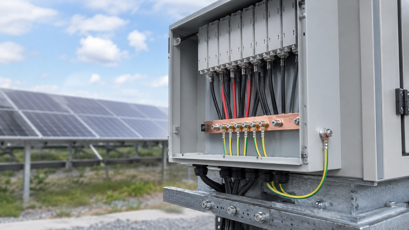
What equipotential bonding is
Equipotential bonding is the practice of connecting all exposed and extraneous conductive parts so they share the same electrical potential. In a combiner box this means the enclosure, the bonding bar, the SPD earth lead and the array frame reference are joined with low-impedance conductors. The aim is that no dangerous voltage appears between any two bonded parts during normal operation or a surge event.
- Connects enclosure, busbar support and SPD earth.
- Removes voltage differences that could cause flashover.
- Forms the backbone of the surge protection scheme.
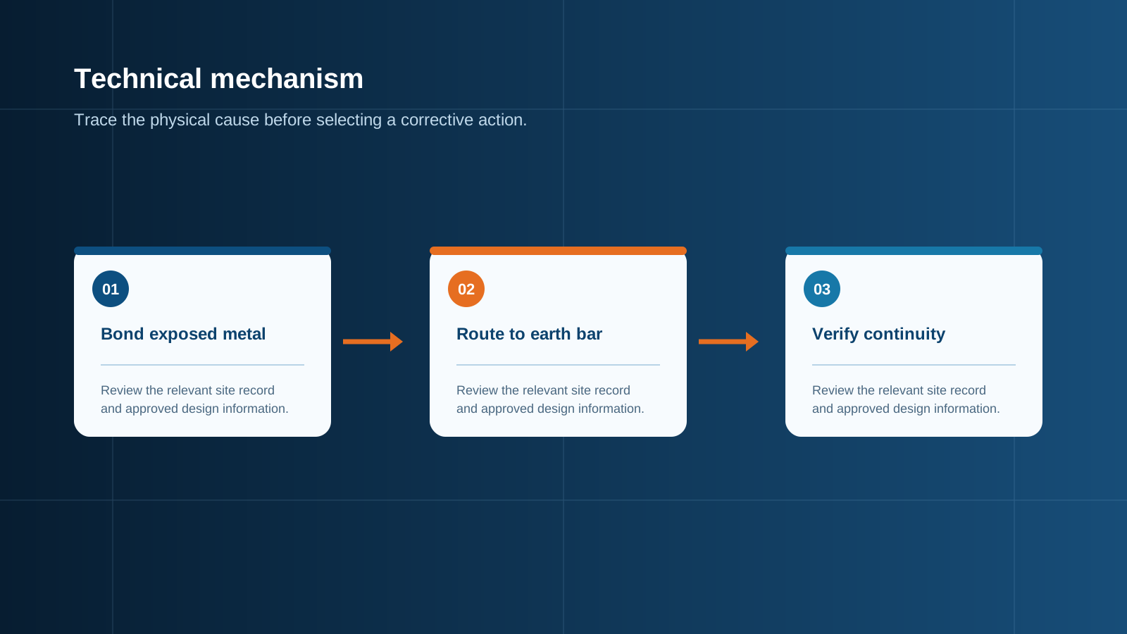
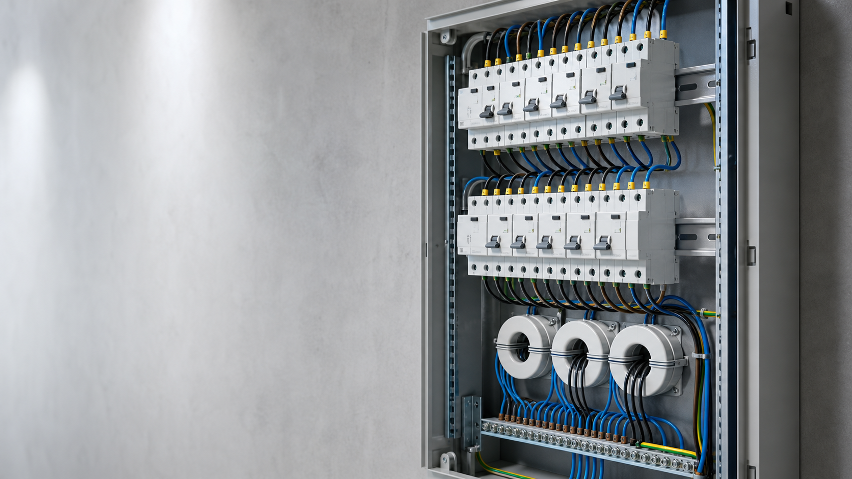
Technical diagram shown at a readable responsive scale.
Enclosure and frame bond
The metal enclosure itself must be part of the bond. The enclosure is connected to the bonding bar, and the array frame reference arriving with the DC cables is likewise tied in. Because the box sits outdoors, its enclosure also provides the mechanical and environmental boundary, so the bond must survive vibration, temperature cycles and corrosion.
- Bond the enclosure to the internal bonding bar.
- Bring the array frame reference onto the same bar.
- Use corrosion-resistant fixings for the long term.
SPD bond
The surge protective device only works if its earth path is solid. The SPD earth lead runs straight to the bonding bar, not to a random screw on the enclosure. A weak SPD bond is the most common reason a properly rated device still fails to protect the busbar.
- Route the SPD earth lead to the bonding bar directly.
- Keep the lead short and low-impedance.
- Confirm the connection at commissioning.
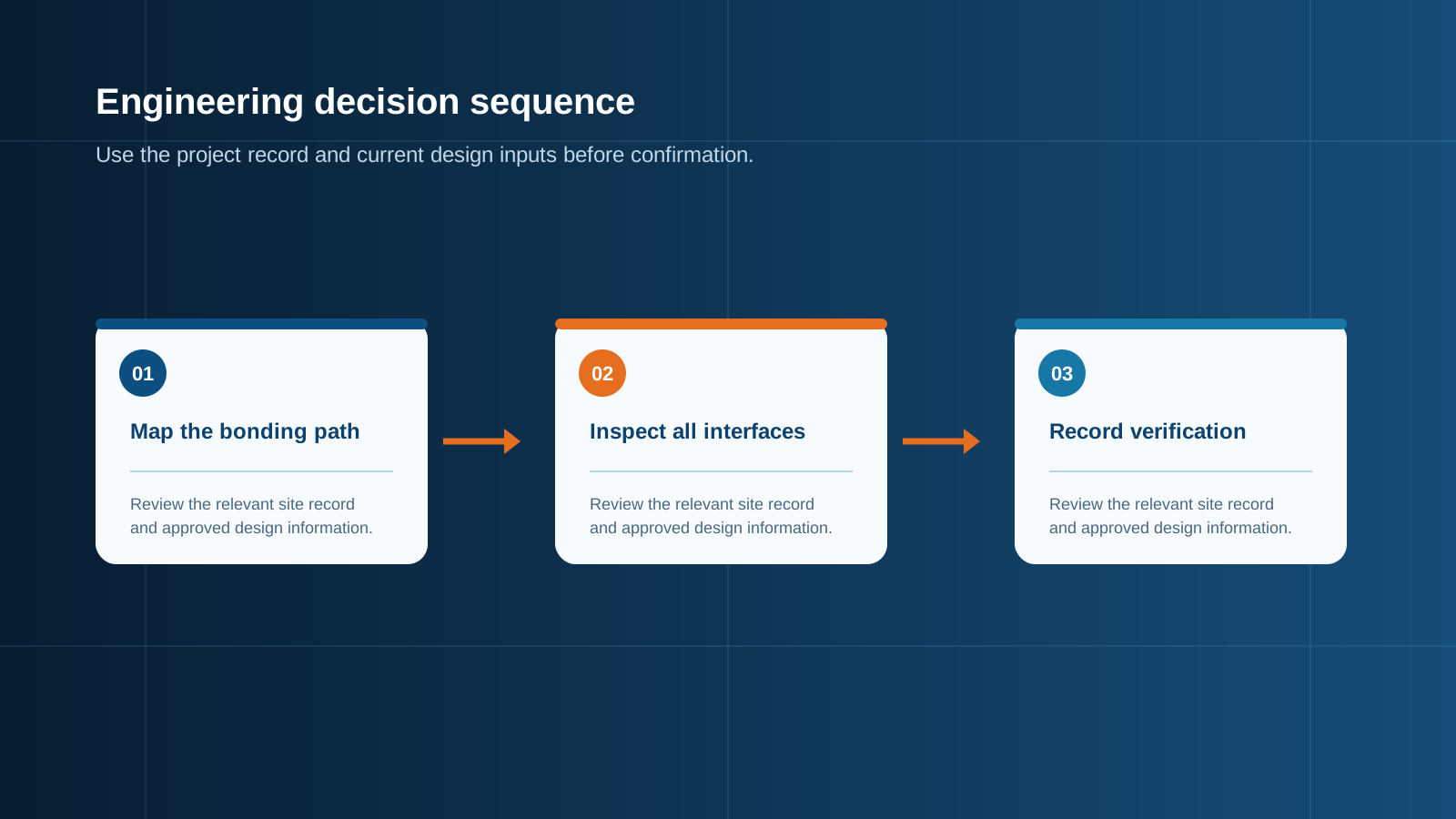
Technical diagram shown at a readable responsive scale.
Cable gland and armour bond
Where armoured cable enters the combiner, the armour must be bonded, not left floating. The cable gland provides that bond, so the gland must be the electrically bonded type and must seat against clean metal. A painted or anodised surface under the gland breaks the bond and must be removed.
- Use bonding-type cable glands on armoured entries.
- Seat the gland on bare, clean metal.
- Treat every cable entry as a bond point.
Bonding conductor size
The bonding conductor must carry the expected fault and surge current without overheating. Size it from the prospective fault current and the relevant wiring rule, and keep it as short as possible because length adds impedance. Where the main protective conductor is already sized for the circuit, the bond usually follows the same cross-section.
- Size from prospective fault and surge current.
- Prefer the shortest practical route.
- Match or exceed the main protective conductor.
Measurement
Bonding quality is verified with a low-resistance ohmmeter or a dedicated bonding tester. Measure the resistance between each bonded part and the bar, and between the bar and the earthing electrode. Values should be within the design limit and consistent across all points.
- Use a low-resistance ohmmeter or bonding tester.
- Measure each bonded part to the bar.
- Record results against the design limit.
Common faults
Most bonding failures are simple and preventable. A loose gland, a painted surface under a fixing, a forgotten armour bond or a long thin earth lead all weaken the scheme. These faults rarely show up until a surge event exposes them, so inspection matters.
- Loose or missing cable-gland bond.
- Paint or oxide breaking a fixing contact.
- Over-long, under-sized earth lead.
Practical checklist
Before the combiner box is closed and energized, walk a short checklist: every metal part bonded to the bar, SPD earth lead short and direct, armour bonded at each gland, conductor size verified, and resistance measured and recorded. This short routine prevents most field failures.
- All metal parts on the bonding bar.
- Short, direct SPD earth lead.
- Measured and recorded bonding resistance.
This is general technical guidance. Confirm final ratings, protection coordination, installation and applicable local requirements against current standards, manufacturer documentation and the approved project design.
Frequently asked questions
What is equipotential bonding in a combiner box?
It is the connection of all metal parts, the enclosure, the SPD earth lead and the array frame reference, to one bonding bar so no dangerous voltage appears between them during operation or a surge.
Why bond the enclosure of a combiner box?
The enclosure is a large conductive surface exposed to the environment. Bonding it removes voltage differences with the internal busbar and gives the SPD a clean return path to earth.
How is the bonding conductor sized?
It is sized from the prospective fault and surge current and kept as short as practical. It normally matches or exceeds the cross-section of the main protective conductor for the circuit.
How do you measure bonding quality?
Use a low-resistance ohmmeter or bonding tester to measure the resistance between each bonded part and the bar, and between the bar and the earthing electrode, against the design limit.
What are common equipotential bonding faults?
Typical faults are a loose or missing cable-gland bond, paint or oxide under a fixing, and an over-long or under-sized earth lead, all of which weaken the surge path.
Discuss your PV combiner requirement
Share the system voltage, string count, inverter interface and installation environment. NEUTRON can review the equipment configuration around your project documentation.
Discuss a projectContinue learning
Explore related technical guidance in Electrical Protection.

Published from the approved Period 09 source package. Technical values and final design decisions must be verified against the current applicable standard, manufacturer documentation and approved project design.