
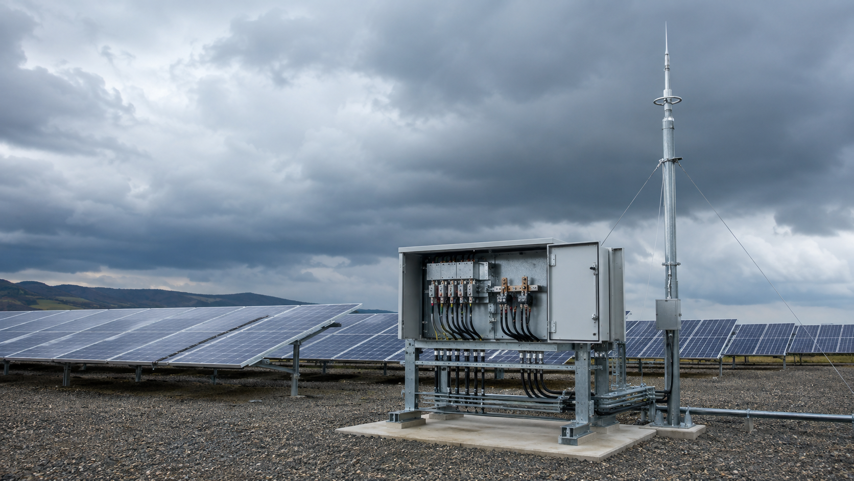
Lightning risk to PV systems
A direct strike or a nearby strike couples energy into the array through two paths: a conducted surge travelling along the DC cables, and an induced surge from the magnetic field. Either path can puncture insulation, weld terminals or destroy the DC disconnect. The risk rises with site lightning density, array area and cable length.
- Direct strike on the array or support structure.
- Nearby strike inducing voltage on long DC runs.
- Ground-potential rise moving through the earthing network.
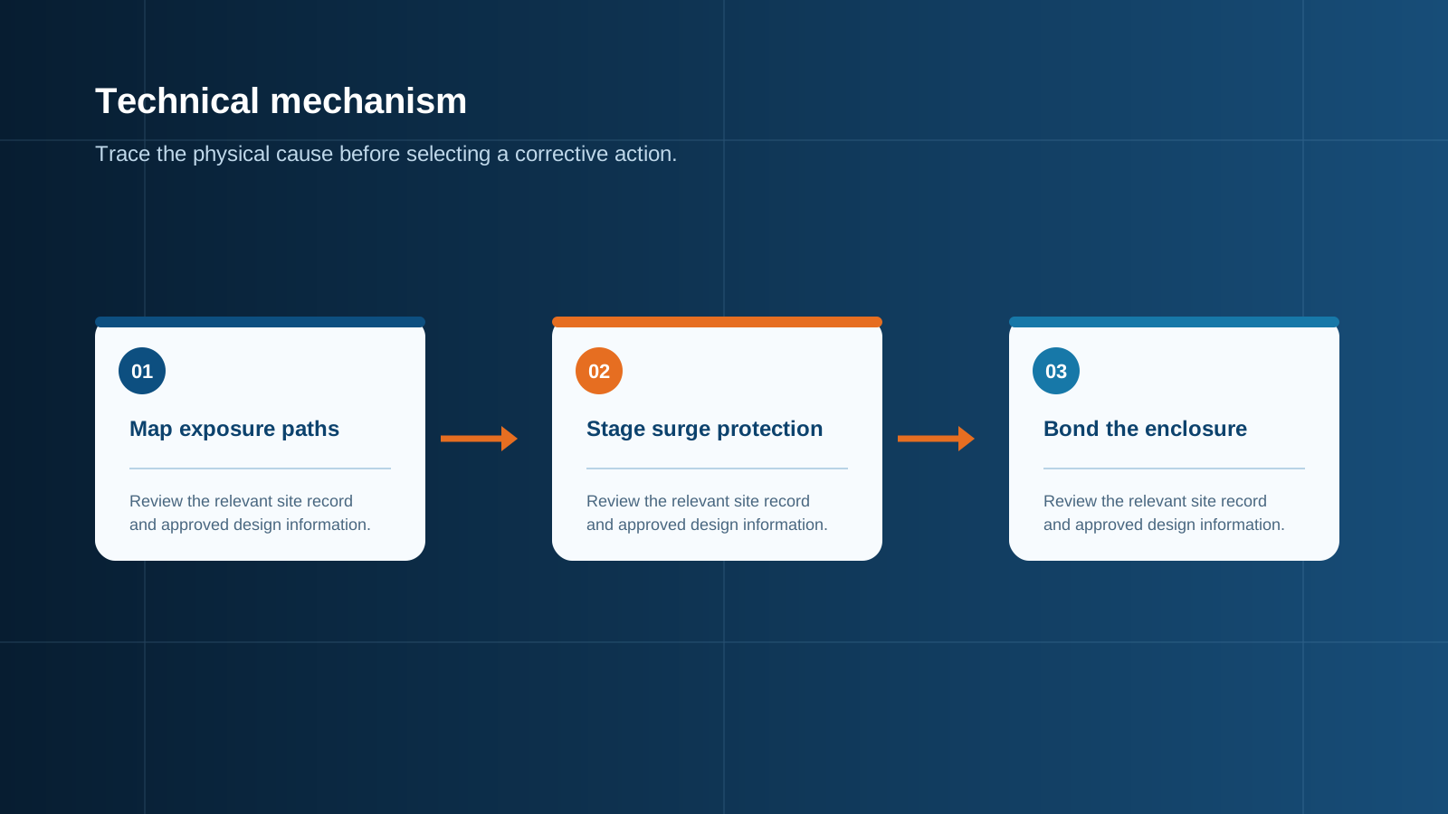
Technical diagram shown at a readable responsive scale.
External LPS and the combiner
An external lightning protection system (LPS) intercepts strikes with air-termination rods and carries the current safely to earth. Where an LPS covers the array, the combiner box must be equipped to handle the associated surge: a Type 1 SPD rated for the 10/350 microsecond direct current waveform becomes necessary. Without an LPS, Type 2 protection against induced surges is usually sufficient.
- LPS present: specify Type 1 or Type 1+2 SPDs.
- No LPS: Type 2 SPDs manage induced surges.
- The combiner enclosure must tolerate the expected thermal and mechanical stress.
The zone transition concept
IEC 62305 introduces the idea of lightning protection zones (LPZ). Outside the structure the surge threat is high; inside an enclosure the threat is reduced. A zone transition is the point where the SPD sits, stepping the exposure level down. Designing around transitions keeps the protected equipment inside a defined, lower-risk zone.
- LPZ 0: open air, full strike exposure.
- LPZ 1: inside the LPS volume, reduced field.
- LPZ 2 and beyond: behind coordinated SPDs, low residual risk.
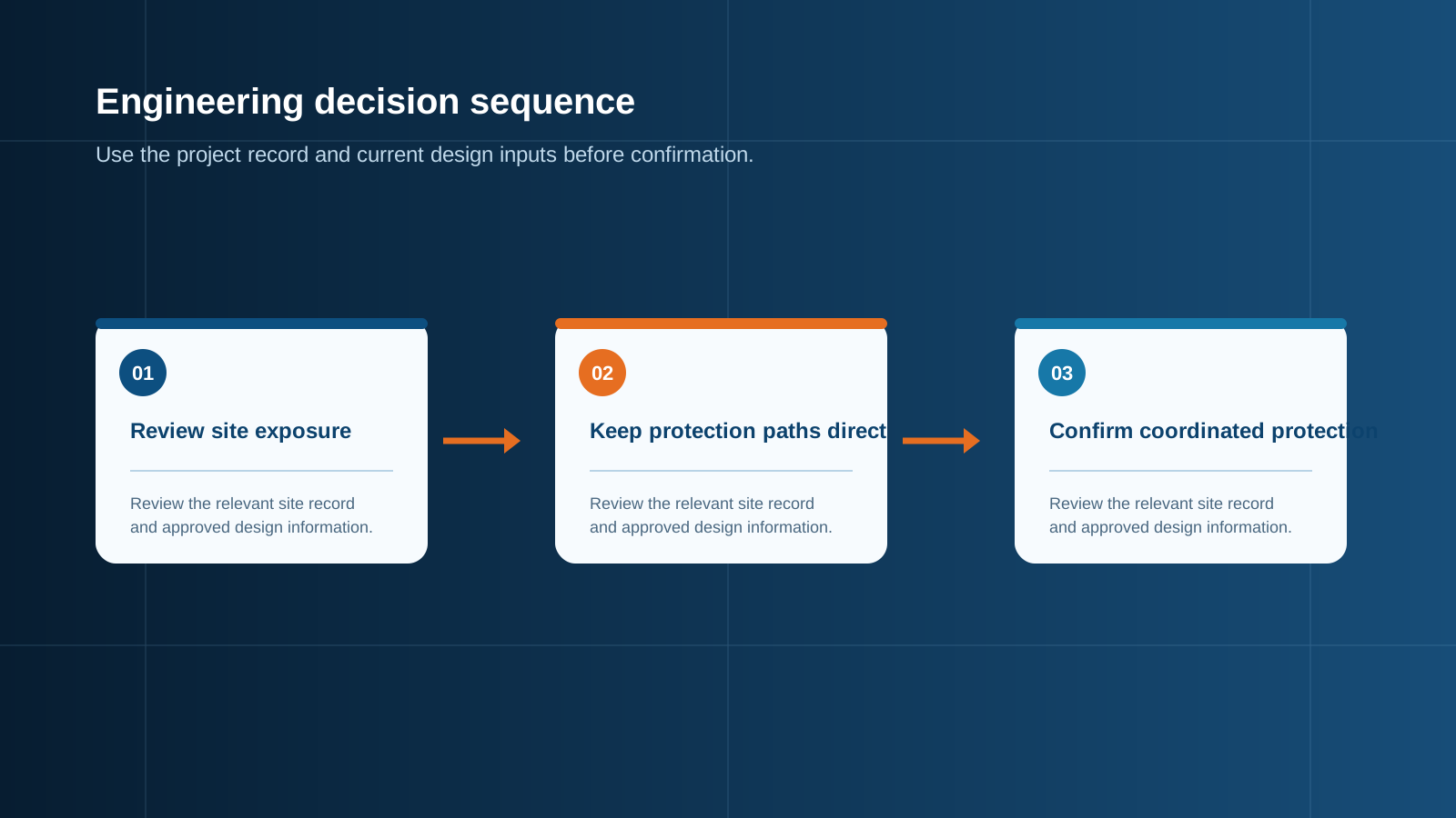
Technical diagram shown at a readable responsive scale.
SPD staging across combiner and inverter
A single SPD rarely covers the whole plant. Staging places protection at each zone transition: a heavy Type 1 or Type 1+2 device at the combiner where the array enters, and a Type 2 device at the inverter or grid-connected cabinet. Each stage reduces the residual surge so the next stage sees a manageable level.
- Combiner stage absorbs the array-side surge.
- Inverter stage trims the residual for sensitive electronics.
- Staged Up values must step downward toward the load.
Equipotential bonding
Bonding joins every metallic part to one reference potential so a surge cannot develop a dangerous voltage difference between them. In the combiner this means the enclosure, the cable armour, the SPD earth lead and the array frame reference all meet at a single bonding bar. Good bonding is what lets the SPD work as designed.
- One bonding bar for enclosure, armour and SPD earth.
- No isolated metal parts left floating.
- Low-impedance path to the earthing system.
Earthing design
The earthing system carries the diverted surge current to earth. Its impedance decides how much voltage appears across the protected equipment during the event. A ring or meshed earth electrode with short, thick conductors performs better than a single long rod, especially on rocky or dry soil.
- Use a low-impedance earthing network.
- Keep earth conductors short and adequately sized.
- Test the earth resistance at commissioning.
Standards that govern the design
Lightning protection for PV is governed by a small set of documents. IEC 62305 covers the overall LPS and zone concept, while IEC 61643-31 covers SPDs for photovoltaic systems. Local wiring rules and the relevant assembly standard (IEC 61439) complete the picture.
- IEC 62305: lightning protection, zones and LPS.
- IEC 61643-31: SPDs for PV systems.
- IEC 61439: low-voltage switchgear and controlgear assemblies.
Design summary
A coordinated lightning protection design starts with the site risk, adds an LPS where needed, places Type 1 or 1+2 SPDs at the combiner zone transition, stages Type 2 devices toward the inverter, and ties everything together with strong bonding and earthing. Done well, the combiner box becomes the reliable first line of defence rather than a weak point.
- Assess site lightning density first.
- Stage SPDs at each zone transition.
- Bond and earth every metallic part.
This is general technical guidance. Confirm final ratings, protection coordination, installation and applicable local requirements against current standards, manufacturer documentation and the approved project design.
Frequently asked questions
Why stage SPDs instead of fitting one large device?
A single device would have to absorb the full array-side surge and still present a low enough residual voltage to the inverter. Staging shares the work: the combiner stage takes the brunt, and the inverter stage trims what remains to a safe level.
What is a lightning protection zone transition?
It is the boundary where the surge exposure level steps down, marked by an SPD. Outside the boundary the field is strong; behind it the equipment sits in a lower-risk zone.
Does every PV site need an external LPS?
No. Sites with low lightning density and no structural LPS can rely on Type 2 SPDs for induced surges. An LPS with Type 1 protection is warranted where direct strikes are a real probability.
Why is equipotential bonding important for lightning protection?
Bonding removes dangerous voltage differences between metal parts during a surge, giving the SPD a clean, low-impedance path to earth and preventing flashover inside the enclosure.
Which standards apply to combiner lightning protection?
IEC 62305 for the LPS and zone concept, IEC 61643-31 for the SPDs, and IEC 61439 for the assembly. Local wiring rules also apply.
Discuss your PV combiner requirement
Share the system voltage, string count, inverter interface and installation environment. NEUTRON can review the equipment configuration around your project documentation.
Discuss a projectContinue learning
Explore related technical guidance in Electrical Protection.

Published from the approved Period 09 source package. Technical values and final design decisions must be verified against the current applicable standard, manufacturer documentation and approved project design.