
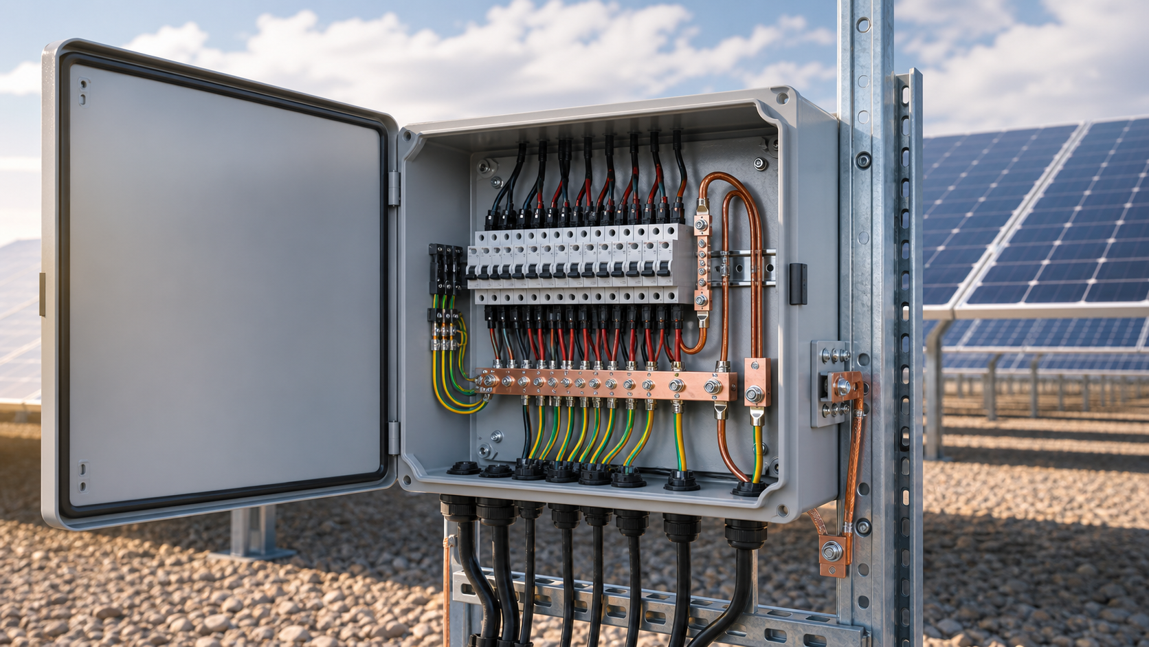
Why grounding matters
The earth connection provides a controlled path for fault current and surge energy so that exposed metal never rises to a dangerous potential. It also gives the SPD a reference to clamp against. Without a sound earth, protection devices cannot operate as designed and personnel are exposed to risk.
- It limits touch voltage on the enclosure during a fault.
- It gives the SPD a low-impedance path to divert surge current.
- It equalises potentials across the array and balance of system equipment.
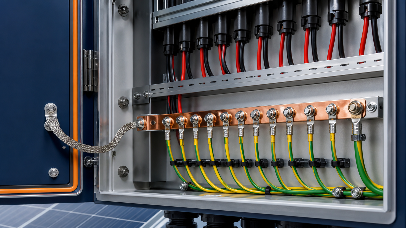
PE terminal and bonding bar
Inside the box, all protective conductors terminate on a dedicated PE bonding bar, not on a random threaded hole. The enclosure body, door, gland plates and the array earth conductor all bond to this bar. The bar must be rated for the prospective fault current and must not be used as a current-carrying conductor in normal operation.
- Use a single, clearly marked PE bar for every protective conductor.
- Bond the door and removable panels so they are never floating.
- Keep the array earth conductor separate from any functional earthing.
Ground resistance target (≤4Ω)
A low earth electrode resistance lets fault and surge energy dissipate quickly. For many PV sites the design target is a ground resistance at or below 4 ohms, confirmed by a fall-of-potential or clamp-on test at the electrode. Higher resistance leaves dangerous touch voltage and weakens SPD performance.
- Measure at the site electrode, not only at the box terminals.
- Where soil is poor, extend the electrode field or add ground enhancement material.
- Re-test after the array is bonded to confirm the combined value.
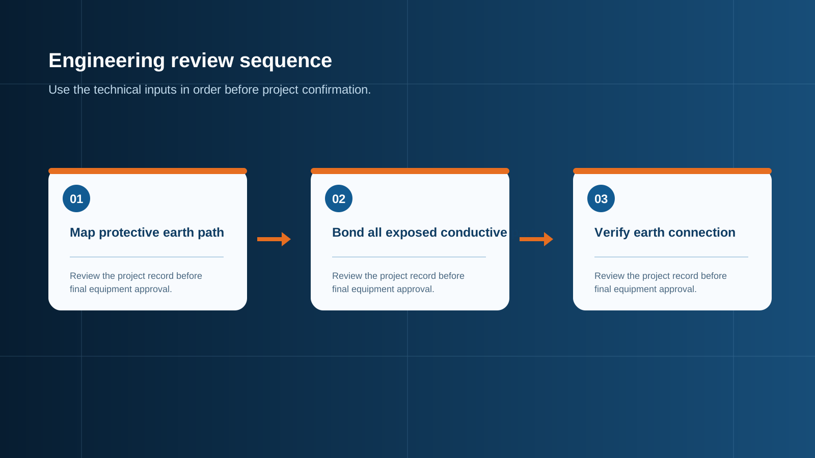
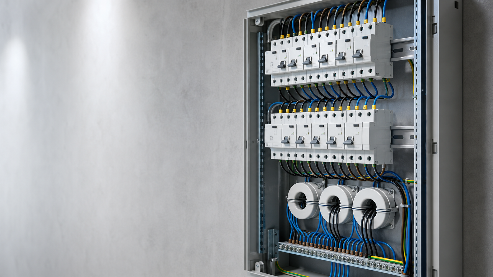
Technical diagram shown at a readable responsive scale.
Conductor size (≥16 mm²)
The protective conductor from the combiner box to the earth electrode must carry fault current without damage. A common minimum for PV earthing is a cross-section of at least 16 mm², with larger sizes where the prospective fault current or cable length demands it. The conductor must be continuous, with no joints that could corrode or loosen.
- Size the earth conductor for the worst-case fault, not the operating current.
- Use a suitably rated, UV-stable conductor for outdoor runs.
- Avoid mixing metals that cause galvanic corrosion at terminations.
SPD grounding
The SPD can only clip a surge if its earth lead is short and low-impedance. Route the SPD earth directly to the PE bar with the minimum length and avoid shared, daisy-chained earth paths. A long or thin SPD earth lead adds inductance that the surge will simply bypass through other equipment.
- Keep the SPD earth lead as short and straight as possible.
- Bond it to the main PE bar, not to a secondary point.
- Verify the SPD earth during the same test as the main bond.
Equipotential bonding
Equipotential bonding ties together every metallic part in the vicinity so that a surge cannot create a voltage difference between them. This includes the combiner box, the supporting structure, the inverter frame and any nearby metallic services. The aim is that everything rises and falls together, protecting both equipment and people.
- Bond the array mounting structure to the same earth system.
- Interconnect neighbouring combiner boxes where the design requires it.
- Include metallic conduit and cable trays in the bond.
Inspection
Earthing must be verified, not assumed. A continuity test confirms every bonded part reaches the electrode, and a resistance test confirms the electrode meets the target. These checks belong in the commissioning record alongside the insulation and voltage tests.
- Continuity test from each bonded point back to the electrode.
- Resistance test of the electrode to the ≤4Ω target.
- Visual check that labels, lugs and torque are as documented.
Site variants
Different sites need different earthing approaches. A coastal plant may need corrosion-resistant conductors and larger electrodes; a rocky site may need deeper or chemically enhanced electrodes; a rooftop may bond to the building earth. The principle is constant — low resistance, continuous bond, short SPD earth — only the method changes.
- Coastal: use corrosion-resistant metals and larger cross-sections.
- Rocky soil: deeper electrodes or ground enhancement material.
- Rooftop: coordinate with the existing building earthing system.
This is general technical guidance. Confirm final ratings, protection coordination, installation and applicable local requirements against current standards, manufacturer documentation and the approved project design.
Frequently asked questions
Why must I bond the combiner box enclosure?
Bonding ties the metal enclosure to the earth system so a fault or surge cannot leave it at a dangerous potential. It protects personnel and gives the protection devices a path to operate.
What is the ground resistance target?
A common design target is a ground electrode resistance at or below 4 ohms, confirmed by on-site testing. Higher resistance weakens fault clearing and SPD performance.
What conductor size should the earth use?
A typical minimum protective conductor cross-section for PV earthing is 16 mm², increased where the fault current or run length requires. It must be continuous and suitably rated for outdoor duty.
How is the SPD grounded correctly?
The SPD earth lead runs directly to the main PE bar by the shortest, straightest route. A long or shared earth path adds inductance and reduces the SPD effectiveness during a surge.
How do I test the grounding on site?
Run a continuity test from every bonded point back to the electrode, then measure the electrode resistance with a fall-of-potential or clamp-on method and confirm it meets the design target.
Discuss your PV combiner requirement
Share the system voltage, string count, inverter interface and installation environment. NEUTRON can review the equipment configuration around your project documentation.
Discuss a projectContinue learning
Explore related technical guidance in Electrical Protection.

Published from the approved Period 09 source package. Technical values and final design decisions must be verified against the current applicable standard, manufacturer documentation and approved project design.