
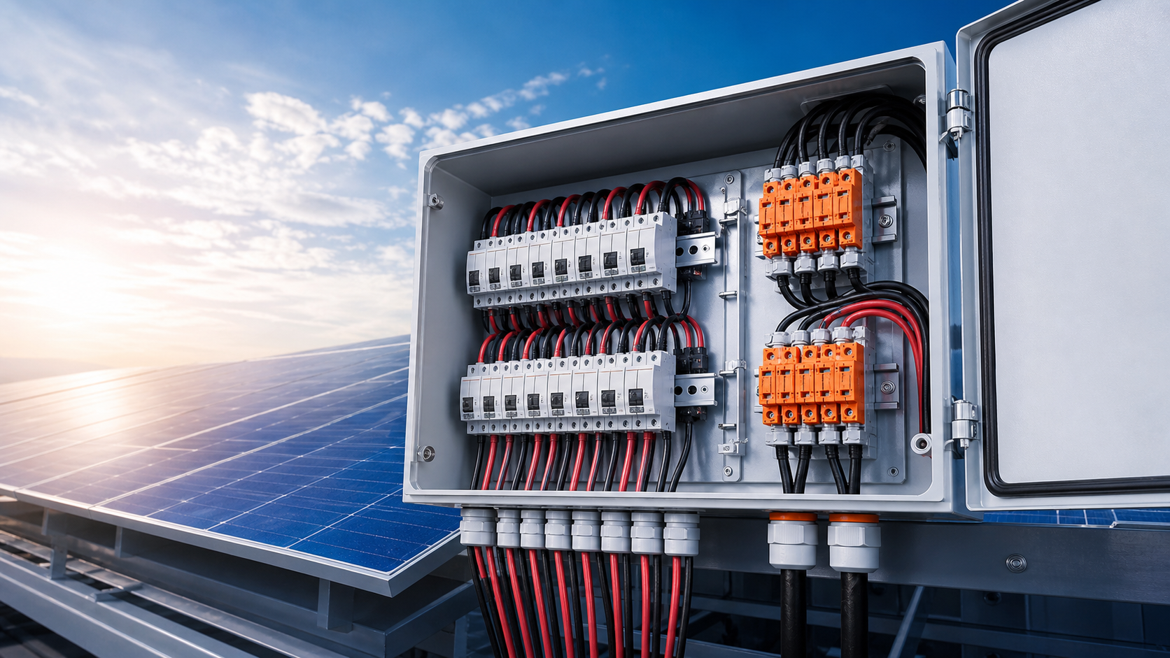
Why input/output configuration decides the design
Every combiner box performs three linked jobs: gather the string inputs, protect each string with its own overcurrent device, and deliver a consolidated DC output to the next stage. The input count and output arrangement are not cosmetic choices — they drive the fuse rating, the busbar cross-section, the enclosure size and the labelling scheme.
- More inputs mean more gPV fuse holders and a larger aggregation bus.
- The output arrangement must match the inverter MPPT architecture, not just the string total.
- A mismatch between box outputs and inverter inputs creates unused terminations or forced parallel runs.
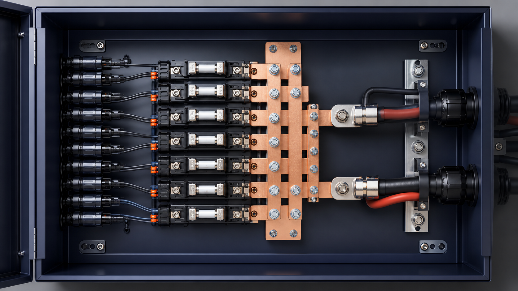
Counting string inputs from the array
Begin with the module layout. Count how many physical strings the array presents to this collection point, where a string is one series chain of modules terminated in a pair of DC conductors. The input count of the box should equal the number of strings you intend to land on that particular enclosure, allowing for the spare positions your project standard requires.
- Read the string count from the single-line diagram, not from the module count.
- Reserve one or two spare inputs on large plants for later array extensions.
- Confirm polarity and conductor size before fixing the input terminal type.
Matching outputs to inverter MPPT inputs
Modern inverters present one or more maximum power point tracking (MPPT) inputs, each of which expects a defined number of paralleled strings. The combiner box output should be planned so that each MPPT receives the correct aggregated current without forcing strings from different orientations onto one tracker. Where the inverter has dual MPPT stages, the box can be wired to feed both.
- Match the number of box outputs to the number of MPPT inputs you will serve.
- Keep strings of the same orientation and similar irradiance on one MPPT.
- Verify the aggregated output current stays within the inverter DC input rating.
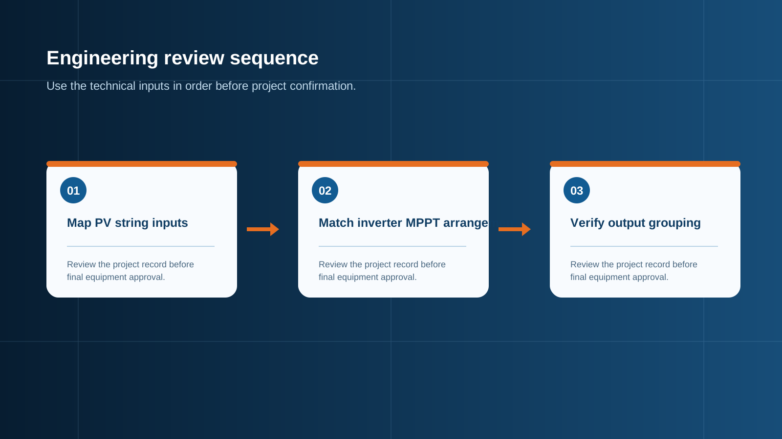
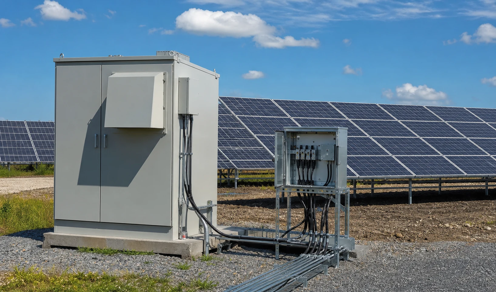
Technical diagram shown at a readable responsive scale.
6-in-1-out versus 6-in-2-out boxes
A "6-in-1-out" box collects six strings and presents a single consolidated DC output, suited to an inverter with one MPPT at that location. A "6-in-2-out" box collects the same six strings but splits them into two output groups, for example three strings per output, so the two outputs can feed two separate MPPT inputs. The choice is decided by the inverter architecture rather than by the string count alone.
- Use 6-in-1-out when a single MPPT receives the full aggregated current.
- Use 6-in-2-out to serve two MPPTs or to balance current between two DC inputs.
- The split must keep each output within its breaker and conductor rating.
Parallel strings and reverse-current duty
When strings are paralleled inside the box, a fault or mismatch on one string can drive reverse current back through the others. This is why each string requires its own gPV fuse: the fuse opens the faulty branch and limits the reverse-current contribution from healthy strings. The configuration must assume the worst-case back-feed from all parallel strings combined.
- Fit a dedicated gPV fuse in every string input path.
- Size the fuse to the string short-circuit current per IEC 60269-6.
- Confirm the busbar and output breaker can survive a reverse-current event.
Cable, gland and enclosure planning
The input and output configuration also sets the cable schedule. Each string input needs a correctly sized gland and sealing, while the output requires conductors rated for the summed current. The enclosure must offer enough entry points and internal space for the chosen layout, plus the corrosion and ingress protection the site demands.
- Select gland sizes for the actual conductor cross-section and cable type.
- Plan conduit entries so inputs and outputs do not share the same unmanaged bundle.
- Choose the IP and corrosion class for the installed environment.
Commissioning and labelling
A clear configuration is only useful if it is documented at the equipment. Permanent labelling should map every input to its string and every output to its destination MPPT, so that fault finding and annual inspection are straightforward. The commissioning record should capture the as-built wiring against the original configuration plan.
- Label each input with its string reference.
- Label each output with the MPPT or cabinet it feeds.
- Keep an as-built drawing with the operation and maintenance documentation.
Specification summary checklist
Before releasing the enquiry, confirm the following against the array design: total string count per box, spare inputs required, MPPT count on the inverter, preferred output split, gPV fuse rating per string, output breaker rating, conductor and busbar capacity, and the site enclosure class. A complete configuration sheet lets the supplier deliver a box built for the modules you are actually installing.
- String inputs and spares defined.
- Output count matched to MPPT inputs.
- Fuse, breaker and busbar sizes confirmed.
- Enclosure and labelling scheme agreed.
This is general technical guidance. Confirm final ratings, protection coordination, installation and applicable local requirements against current standards, manufacturer documentation and the approved project design.
Frequently asked questions
How many string inputs do I need on a combiner box?
The input count equals the number of module strings landed on that enclosure, plus any spares your project standard requires. Read the figure from the single-line diagram rather than the total module count.
What does 6-in-2-out mean on a combiner box?
It means the box collects six string inputs and presents two separate DC outputs, typically to feed two inverter MPPT inputs or to balance current between two DC stages, with each output remaining within its own protection rating.
Can one combiner box feed two inverters?
A box can feed two inverter MPPT inputs if it is configured with two outputs and each output is rated for the current it carries. Feeding two separate inverter units from one enclosure is possible only when the outputs are independently protected and the wiring is documented.
Does the input count change the fuse rating?
The input count does not change the per-string fuse rating, which is set by the string short-circuit current. It does change the aggregated output current and therefore the output breaker, busbar and conductor sizing.
How do I size the combiner box output?
Size the output for the sum of the protected string currents it aggregates, then select the output breaker, conductor and busbar within that figure and the inverter DC input limit, allowing for the thermal and derating margin of the installation.
Discuss your PV combiner requirement
Share the system voltage, string count, inverter interface and installation environment. NEUTRON can review the equipment configuration around your project documentation.
Discuss a projectContinue learning
Explore related technical guidance in Solar PV.

Published from the approved Period 09 source package. Technical values and final design decisions must be verified against the current applicable standard, manufacturer documentation and approved project design.