
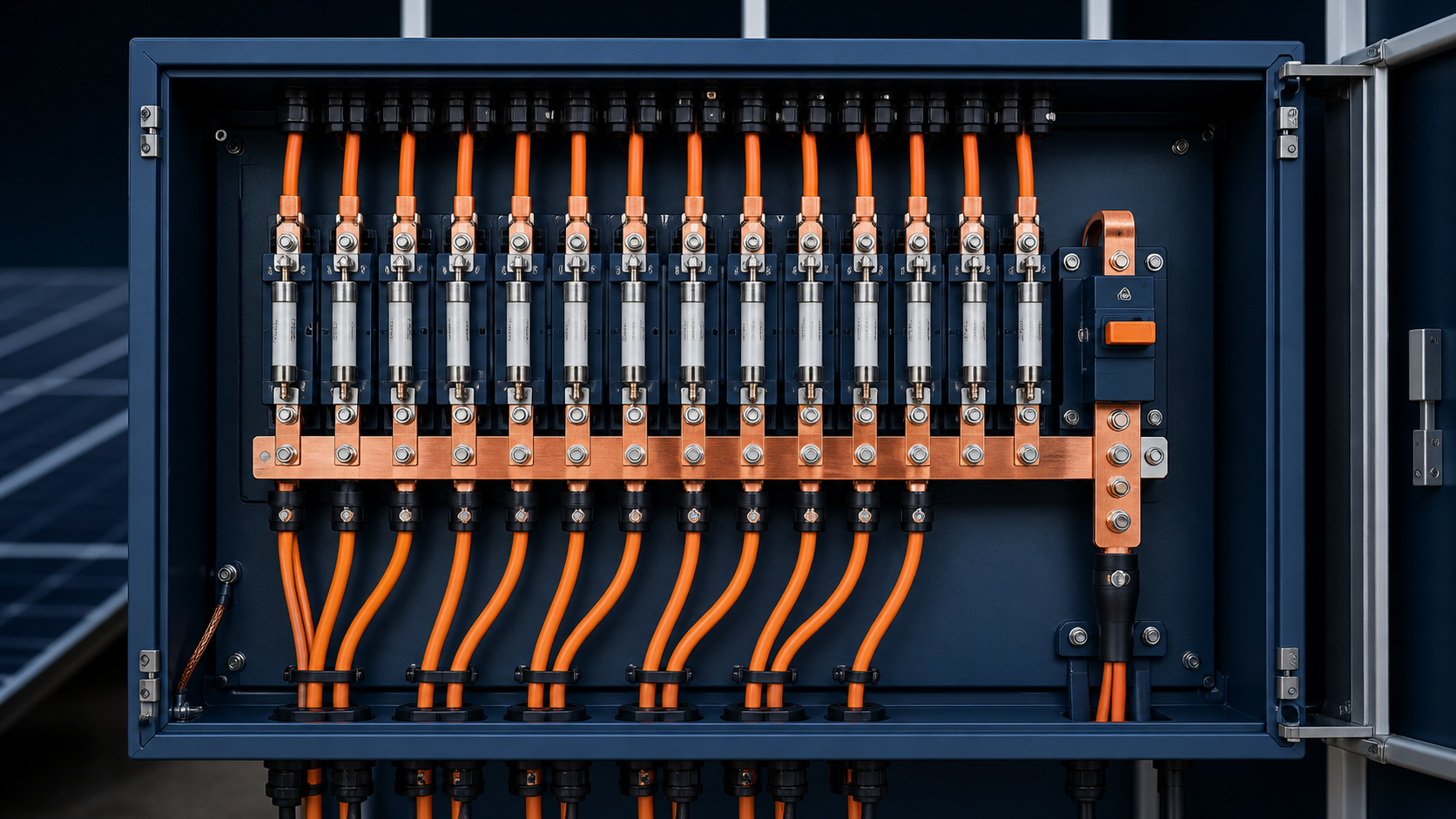
What the busbar does
The busbar carries the sum of all protected string currents from the input fuses to the output breaker and terminal. It is a continuous conductive path that must stay within its temperature limit under the worst-case array output, including any rear-side gain on bifacial modules. Because it aggregates every string, its rating is always higher than any single string fuse.
- Collects fused string currents into one output.
- Must survive the summed continuous current.
- Sets the thermal ceiling for the enclosure interior.
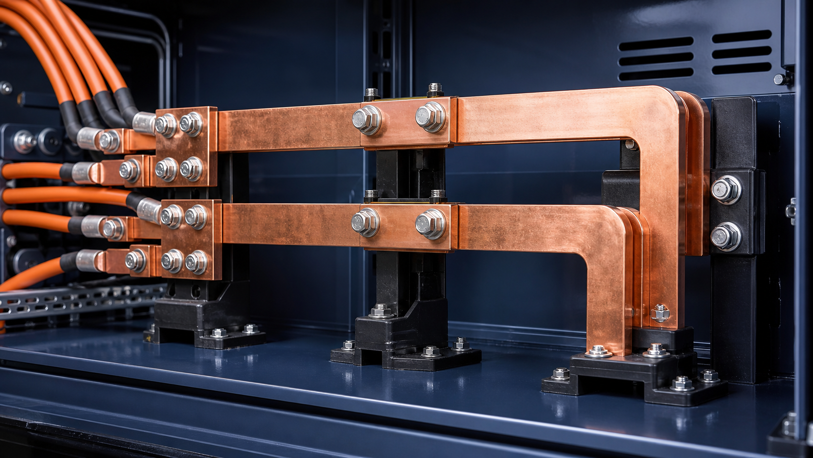
Aggregated output current calculation
Start from the string short-circuit current (Isc) of one module string, apply the 1.25× factor used for gPV fuse selection, and multiply by the number of paralleled strings landing on the box. The result is the aggregated current the busbar must carry continuously. Always use the project maximum, not the nameplate minimum, so the design keeps margin under peak irradiance.
- I_bus = N_strings × 1.25 × Isc_string.
- Use the bifacial-inclusive peak Isc where applicable.
- Round up to the next standard busbar rating.
Cross-section and material (copper)
Copper is the standard busbar material because of its high conductivity and mechanical stability under thermal cycling. The required cross-section follows from the aggregated current and the permitted current density, with copper typically carrying a known ampacity per square millimetre at a stated temperature rise. A larger cross-section lowers resistance, reduces heating and improves fault withstand.
- Copper offers better conductivity than aluminium for the same size.
- Cross-section is chosen from aggregated current and allowed rise.
- Busbar thickness also affects mechanical rigidity and termination.
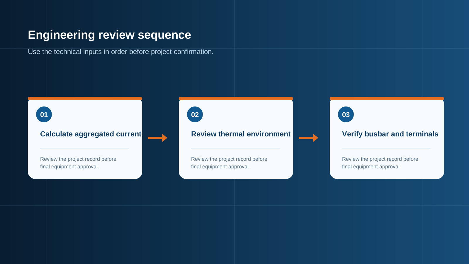
Technical diagram shown at a readable responsive scale.
Temperature rise and derating
Every busbar has a rated temperature rise above ambient at its continuous current. The enclosure environment, the proximity of other heat emitters such as the SPD and disconnect, and any solar gain on the box all eat into that budget. When the site is hot or the enclosure is tightly packed, the usable ampacity must be derated so the conductor never exceeds its insulation and termination limits.
- Define the maximum ambient for the installed site.
- Account for internal heat from other devices.
- Apply a derating factor before fixing the cross-section.
Torque and termination limits
A busbar is only as reliable as its connections. Each termination has a specified torque and a maximum continuous current per contact; under-sized or loose joints create hot spots that degrade the bus over time. The termination rating must match the busbar rating, and the torque must be set with a calibrated tool during assembly.
- Match termination current to busbar current.
- Use the specified torque with calibrated tooling.
- Re-check torque as part of commissioning.
Layout and spacing
The physical layout affects both cooling and dielectric performance. A busbar needs adequate clearance to the enclosure and to other live parts, plus enough spacing between parallel buses to avoid mutual heating. Good layout also keeps the conductor runs short and the terminations accessible for inspection.
- Keep clearance for the system voltage class.
- Avoid crowding that traps heat.
- Make terminations reachable for maintenance.
Verification before shipment
Before the box leaves the factory, the busbar rating should be verified against the calculated aggregated current, the termination torque recorded, and the temperature rise confirmed by test or by reference to a qualified design. This verification is what turns a generic copper bar into a documented, compliant current path.
- Check cross-section against aggregated current.
- Record termination torque values.
- Confirm temperature-rise qualification.
Worked sizing example
Consider a box collecting 12 strings, each with a peak Isc of 16 A. Applying 1.25× gives 20 A per string, so the aggregated bus current is 12 × 20 A = 240 A. Selecting a copper busbar with a continuous rating above 240 A at the permitted temperature rise, and confirming the terminations and torque match, yields a compliant design. If the site ambient is high, the cross-section is increased to preserve the same rise.
- Isc per string: 16 A, with 1.25× = 20 A.
- 12 strings → 240 A aggregated.
- Choose copper bus rated above 240 A at the rise limit.
This is general technical guidance. Confirm final ratings, protection coordination, installation and applicable local requirements against current standards, manufacturer documentation and the approved project design.
Frequently asked questions
How do I calculate the busbar current?
Multiply the number of paralleled strings by the protected string current, using 1.25 × Isc per string and the project peak including any bifacial gain. The result is the aggregated continuous current the busbar must carry.
Why is copper used for combiner box busbars?
Copper gives high conductivity, stable termination performance under thermal cycling and good mechanical rigidity, which together support a reliable, low-loss current path inside the enclosure.
What temperature rise is allowed on the busbar?
The permitted rise is set by the busbar rating and the insulation or termination limits of the assembly; the design must keep the conductor within that rise at the site ambient after derating.
Does the number of strings change the busbar size?
Yes. Because the bus carries the sum of all string currents, adding strings raises the aggregated current and therefore demands a larger cross-section or a higher-rated bus.
How is the busbar verified before shipment?
The cross-section is checked against the aggregated current, termination torque is recorded, and the temperature-rise qualification is confirmed by test or by reference to a qualified design.
Discuss your PV combiner requirement
Share the system voltage, string count, inverter interface and installation environment. NEUTRON can review the equipment configuration around your project documentation.
Discuss a projectContinue learning
Explore related technical guidance in Solar PV.

Published from the approved Period 09 source package. Technical values and final design decisions must be verified against the current applicable standard, manufacturer documentation and approved project design.