
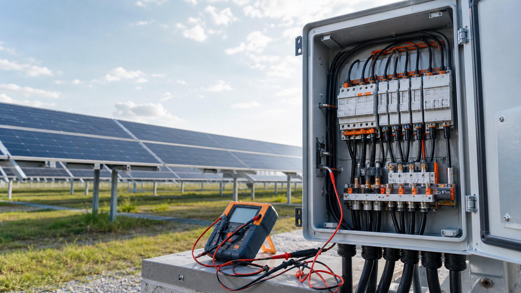
Pre-energise safety
Before any measurement, confirm the box is de-energised and isolated. The DC disconnect stays OFF, personal protective equipment is worn, and the work area is barriered. No test is worth a shock.
- Verify the DC disconnect is in the OFF position and locked where required.
- Confirm fuses are seated but the output toward the inverter remains open.
- Check that warning labels and the disconnect marking are in place.
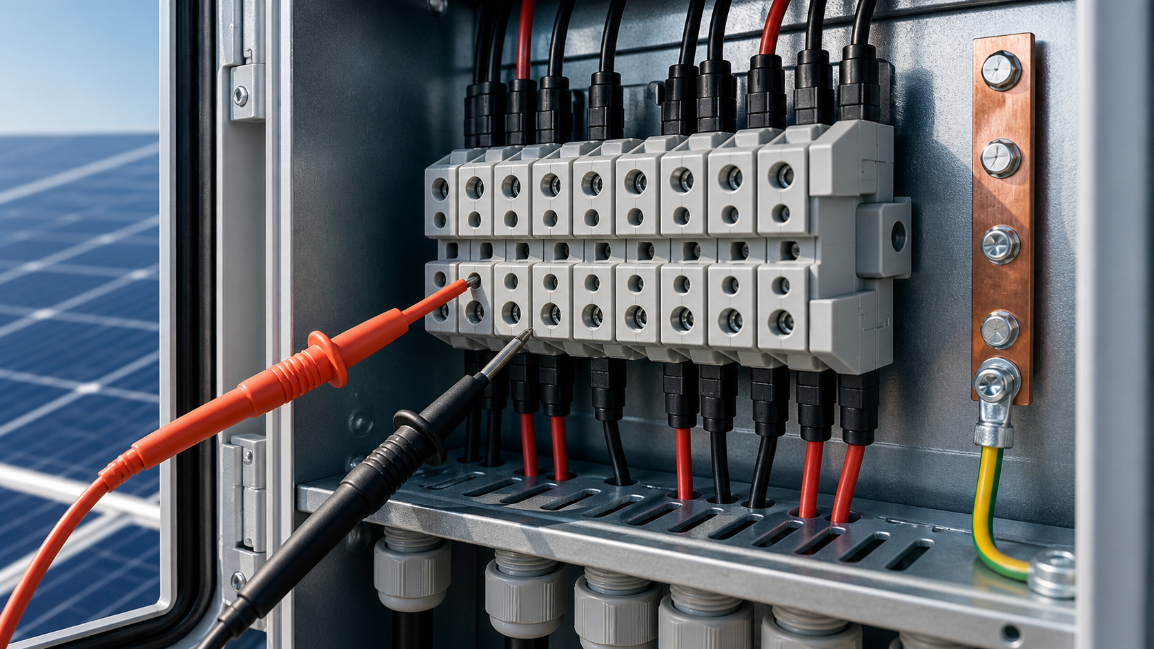
Insulation resistance test (≥20 MΩ)
An insulation resistance test between each conductor and earth, and between positive and negative rails, confirms there is no low-resistance fault path. A typical acceptance value is at least 20 MΩ at the test voltage, with no downward trend that would suggest damp or contamination.
- Use a DC insulation tester suited to the system voltage.
- Test each string pair and the combined bus to earth.
- Investigate any reading below the acceptance limit before proceeding.
Per-string open-circuit voltage
With the inverter side still open, measure the open-circuit voltage (Voc) of every string at the combiner input. Each value should match the module datasheet for the measured conditions, within tolerance, and all strings in an array should be closely matched.
- Record Voc per string and compare against the expected design value.
- Flag any string that is open, shorted or far from its neighbours.
- Confirm the measured sum at the bus does not exceed the equipment rating.
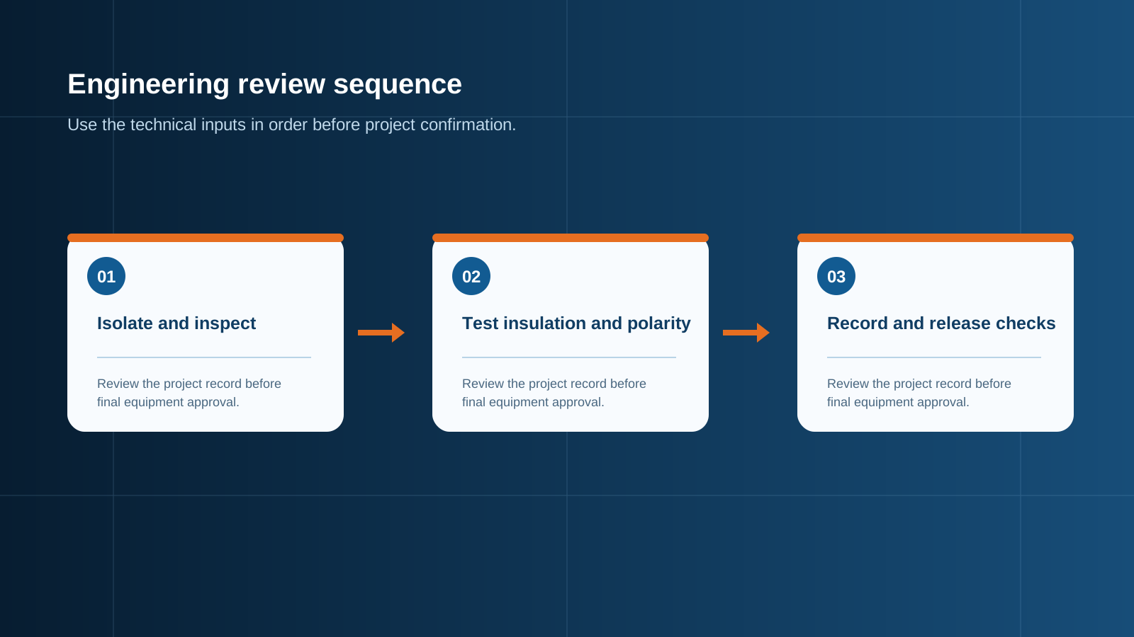
Technical diagram shown at a readable responsive scale.
Polarity and reverse-check
Confirm every string enters with the correct polarity: positive to the + bus, negative to the − bus. A reverse-connected string cancels current and can stress the busbar. The polarity check is a simple multimeter verification before the isolator is closed.
- Verify S n+ reads positive relative to S n− at each input.
- Check that the output polarity matches the inverter requirement.
- Correct any reversed pair before energising.
Breaker and SPD status
Confirm the DC disconnect operates smoothly and shows the correct state, and that the SPD is healthy with its status indicator in the normal range. A tripped or degraded SPD should be replaced before the box is handed over.
- Exercise the disconnect to confirm mechanical operation.
- Read the SPD status window and record the condition.
- Confirm the SPD earth bond is continuous.
Torque verification
Re-check the torque on the main power terminals and the earth bond. Thermal cycling and handling can loosen terminations; a torque verification at commissioning prevents the hotspots that appear months later. Use the values stated on the rating plate.
- Verify output busbar and string terminal torque.
- Verify the PE bonding bar and earth conductor torque.
- Mark or log each checked termination.
Sealing and labelling
Before sign-off, confirm the enclosure is sealed to its IP rating and every label is present: box identity, string schedule, disconnect marking and SPD status. A sealed, labelled box is safer to operate and faster to maintain.
- Confirm all cable glands are tightened and sealed.
- Confirm the door gasket is seated and the door closes square.
- Confirm the internal schematic and string labels are fitted.
Sign-off
Sign-off records that every step passed and the box is ready for energisation. The commissioning engineer retains the measured values, the torque log and the as-built label set. Only then is the DC isolator closed and the inverter side brought online.
- Attach the insulation, Voc and polarity records.
- Attach the torque verification log.
- Obtain the responsible engineer sign-off before energising.
This is general technical guidance. Confirm final ratings, protection coordination, installation and applicable local requirements against current standards, manufacturer documentation and the approved project design.
Frequently asked questions
What insulation resistance value is acceptable?
A typical acceptance value is at least 20 MΩ measured at the appropriate DC test voltage, with no downward trend that would indicate moisture or contamination. Lower values must be investigated first.
Why measure open-circuit voltage per string?
Per-string Voc confirms each string is intact and matched to its neighbours. A missing or reversed string shows up immediately, and the summed value confirms the bus stays within the equipment rating.
How is polarity tested at commissioning?
With a multimeter at each input, confirm S n+ is positive relative to S n− and that the output polarity matches the inverter requirement. Any reversed pair is corrected before the isolator is closed.
Why verify torque during commissioning?
Terminations can loosen from handling and thermal cycling. A torque check at commissioning prevents high-resistance hotspots that would otherwise appear after the plant has run for some time.
What belongs in the sign-off record?
The sign-off record holds the insulation, Voc and polarity results, the torque verification log, and the as-built label set, with the responsible engineer approval before energising.
Discuss your PV combiner requirement
Share the system voltage, string count, inverter interface and installation environment. NEUTRON can review the equipment configuration around your project documentation.
Discuss a projectContinue learning
Explore related technical guidance in Solar PV.

Published from the approved Period 09 source package. Technical values and final design decisions must be verified against the current applicable standard, manufacturer documentation and approved project design.