
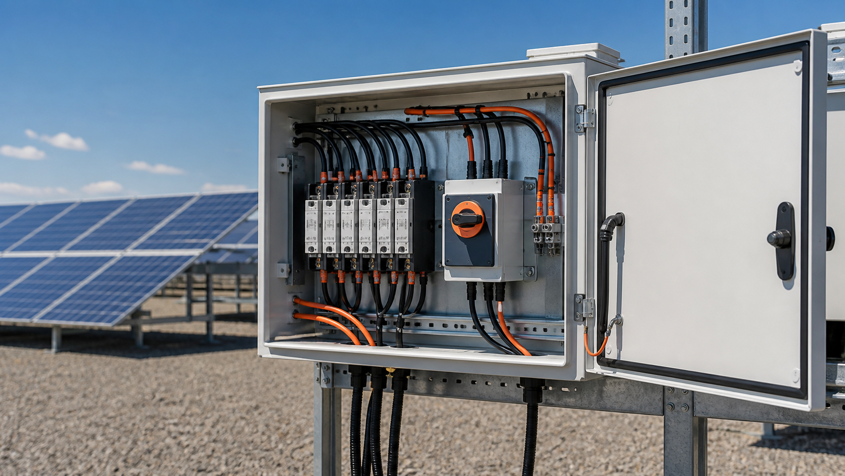
Why a DC isolator in the combiner
Unlike a grid supply that can be switched off at the origin, a solar array keeps generating as long as it is illuminated. The combiner box isolator gives a defined, visible break so that the enclosed busbar and string fuses can be worked on safely. It is a life-safety device as much as a switching component.
- Provides a visible, reliable disconnect point.
- Lets the box be isolated without waiting for darkness.
- Supports safe maintenance of fuses and busbar.
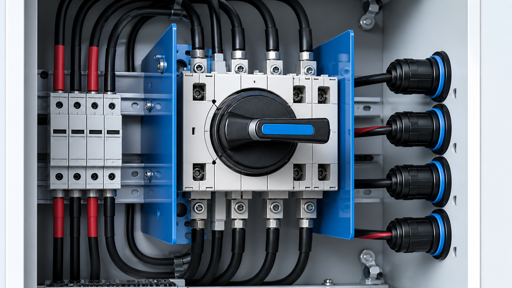
Voltage and current rating
The isolator must be rated for the system voltage class (1000 V or 1500 V DC) and for the aggregated output current of the box. Selecting below the system voltage risks breakdown, while undersizing the current rating leads to overheating at the contacts. Both figures should be taken from the as-built configuration, not from a generic assumption.
- Match the DC voltage class exactly.
- Rate the current for the aggregated output.
- Keep margin for future string additions.
DC arc-breaking capability
Direct current does not pass through a natural zero crossing as often as alternating current, so an arc drawn during switching is harder to extinguish. A DC-rated isolator is built with magnetic blow-out or extended contact travel to quench that arc. Specifying an AC switch here is a serious error that can weld contacts or cause a sustained arc.
- Require a certified DC breaking rating.
- Verify the arc-quenching method.
- Never substitute an AC switch for DC duty.
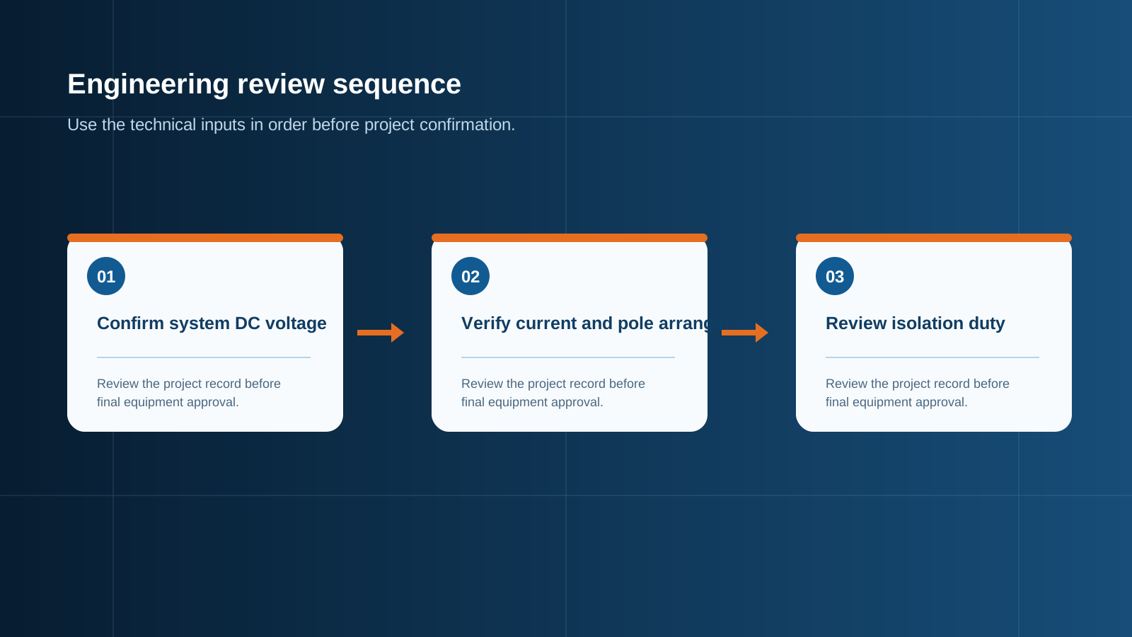
Technical diagram shown at a readable responsive scale.
Pole and switching arrangement
The pole count must match the number of conductors to be switched. For a two-wire PV string this is typically a two-pole device, while a three-pole or four-pole arrangement may be used where the design switches multiple conductors. All poles should open together so no live conductor remains unexpectedly connected.
- Match poles to the conductor count.
- Ensure all poles open simultaneously.
- Confirm the arrangement with the wiring diagram.
IP and environmental rating
The isolator often sits at the enclosure front or in a weather-exposed position, so its ingress and corrosion protection must suit the site. A coastal or desert installation demands a higher protection class than a mild-climate rooftop. The handle and shaft seals are part of this rating and should not be downgraded.
- Select IP rating for the installed environment.
- Choose corrosion class for coastal or desert sites.
- Keep handle seals intact to preserve the class.
Handle and safety interlock
A clear handle position and, where required, a padlockable interlock prevent accidental re-energisation during work. The handle should show open and closed states unambiguously, and the interlock should let the box be locked in the open position for the duration of a task.
- Use a clearly marked ON/OFF handle.
- Provide a padlockable interlock for isolation.
- Confirm the status is visible at a glance.
Standards (IEC 60947-3)
Switch-disconnectors for low-voltage circuits are covered by IEC 60947-3, which sets the construction, temperature-rise and switching requirements for devices used as isolators. Selecting a unit verified to this standard gives confidence that the rated breaking and isolation performance is real rather than claimed.
- IEC 60947-3 governs switch-disconnectors.
- Look for verified temperature-rise data.
- Pair with the broader IEC 61439 assembly rules.
Selection table
A practical selection starts from four numbers: system voltage class, aggregated current, required DC breaking capacity and pole count, then filters by IP and site class. The table below summarises the typical mapping from array size to isolator specification for a combiner box application.
- 1000 V / up to ~125 A → 2-pole DC switch-disconnector, IP65.
- 1500 V / up to ~250 A → 2-pole DC switch-disconnector, higher isolation.
- Coastal site → add corrosion-rated enclosure and sealed handle.
- Maintenance-heavy → padlockable interlock as standard.
This is general technical guidance. Confirm final ratings, protection coordination, installation and applicable local requirements against current standards, manufacturer documentation and the approved project design.
Frequently asked questions
Why must the isolator be DC-rated?
Photovoltaic direct current lacks frequent natural zero crossings, so an arc drawn during switching is hard to extinguish. A DC-rated switch-disconnector is built to quench that arc; an AC switch can weld or sustain arcing.
What DC breaking capacity is needed?
The isolator must be able to break the maximum DC current it may see at the combiner output under a switching or fault condition, matched to the system voltage class and the aggregated string current.
How should the poles be arranged?
The pole count should match the number of conductors being switched, with all poles opening together so no live conductor remains connected when the box is isolated.
Which IP rating should I choose?
Choose the IP rating for the installed environment: a higher class for coastal, desert or exposed sites, and confirm the handle and shaft seals preserve that rating.
Which standard applies to the DC isolator?
IEC 60947-3 covers switch-disconnectors for low-voltage circuits, including the temperature-rise and switching requirements relevant to combiner box isolation.
Discuss your PV combiner requirement
Share the system voltage, string count, inverter interface and installation environment. NEUTRON can review the equipment configuration around your project documentation.
Discuss a projectContinue learning
Explore related technical guidance in Electrical Protection.

Published from the approved Period 09 source package. Technical values and final design decisions must be verified against the current applicable standard, manufacturer documentation and approved project design.