
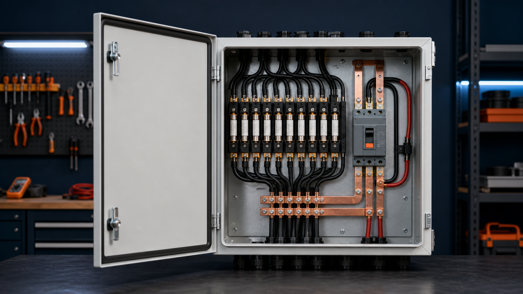
Output protection role
Each string inside the box is defended by its own gPV fuse, but the consolidated output still requires a device that can clear a fault on the common bus and a switch that can disconnect the whole box. The output breaker or fused switch is the final barrier before the DC leaves the enclosure.
- Clears faults on the aggregated output bus.
- Provides a disconnect point for safe isolation.
- Complements, but does not replace, the per-string fuses.
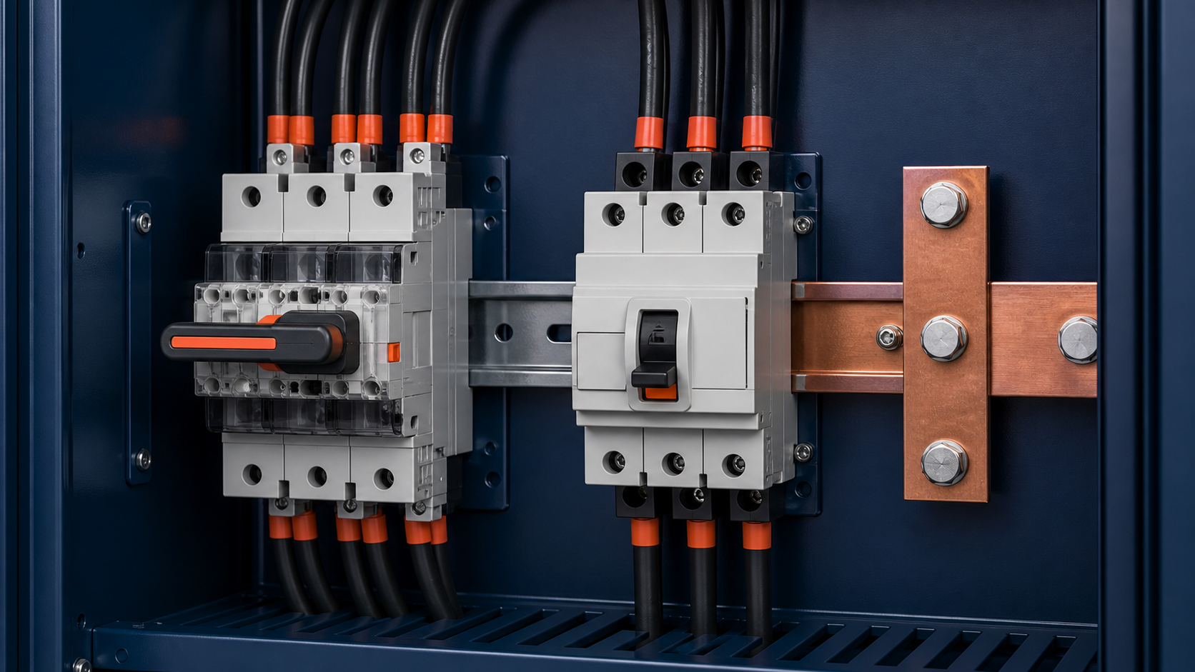
Aggregated current versus per-string current
The output device sees the sum of the protected string currents, not the current of one string. Sizing starts from the aggregated value: the number of strings multiplied by the protected per-string current (1.25 × Isc). The output rating must exceed this continuous load while still tripping on a genuine overcurrent of the bus.
- Output current = N_strings × 1.25 × Isc.
- Per-string fuses stay sized to the individual string.
- The output breaker is set above the aggregated load.
Choosing a DC-rated breaker/isolator
Standard alternating-current breakers are not suitable for photovoltaic duty because DC arcs do not pass through a natural zero crossing as often. A DC-rated circuit breaker or switch-disconnector must be selected, with a voltage rating at or above the system class (1000 V or 1500 V) and a current rating that covers the aggregated output.
- Use only DC-rated devices for the output.
- Match the voltage class to the system.
- Confirm the continuous current rating exceeds the load.
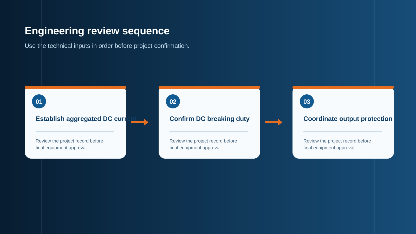
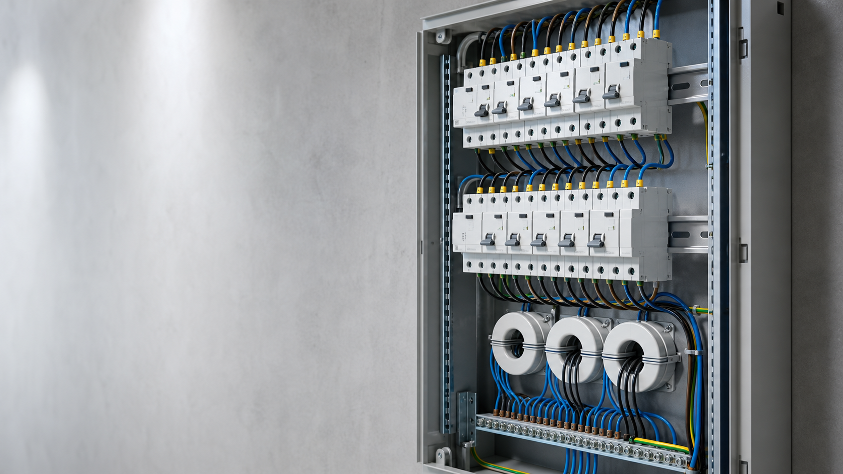
Technical diagram shown at a readable responsive scale.
Breaking capacity for DC faults
Under a fault, the output device may have to interrupt a high DC current while quenching a sustained arc. The rated breaking capacity must exceed the prospective fault current at that point, which can be substantial given the low system impedance of many paralleled strings. Underspecifying this figure is a common and dangerous omission.
- Determine the prospective DC fault current at the output.
- Select a breaking capacity above that figure.
- Remember DC arcs are harder to clear than AC arcs.
Coordination with string fuses
The output protection and the per-string gPV fuses must be coordinated so that a fault on one string is cleared by that string's fuse, while a fault on the common bus is cleared by the output device. Good coordination prevents a single-string event from tripping the whole array offline and avoids nuisance operation of the output breaker.
- String fuse clears its own branch fault.
- Output breaker clears a bus or feeder fault.
- Selective coordination keeps healthy strings online.
Main switch versus fused switch
A plain disconnect switch isolates but does not protect; a fused switch adds a backup fuse in the output path. Where the output breaker already provides protection, a switch-disconnector may be enough, but a fused switch offers an additional barrier if the breaker is omitted or as a maintenance isolation point. The choice depends on the overall protection concept of the array.
- Switch-disconnector: isolation only.
- Fused switch: isolation plus backup fusing.
- Match the concept to the inverter and cabinet design.
Field setting
On site, the output device must be set and labelled to match the as-built configuration. The configured rating should reflect the real aggregated current and the verified fault level, and the isolation point should be clearly marked so operators can de-energise the box without ambiguity. Torque and indication state should be confirmed during commissioning.
- Label the output rating and isolation point.
- Confirm torque and contact state.
- Record the setting in the commissioning documentation.
Sizing checklist
Before release, confirm the output voltage class, the aggregated continuous current, the required DC breaking capacity, the coordination with string fuses, and whether a fused or unfused switch is used. A complete checklist lets the supplier deliver an output stage built for the actual array rather than a generic feeder.
- Voltage class: 1000 V or 1500 V.
- Aggregated current from string count.
- DC breaking capacity verified.
- Coordination with gPV string fuses confirmed.
This is general technical guidance. Confirm final ratings, protection coordination, installation and applicable local requirements against current standards, manufacturer documentation and the approved project design.
Frequently asked questions
How is output protection different from string protection?
String protection uses a gPV fuse on each individual string, while output protection defends the consolidated feeder with a DC-rated breaker or fused switch sized for the aggregated current.
Why does the DC breaking capacity matter?
A DC fault sustains an arc that is harder to clear than an AC fault, so the output device must be rated to interrupt the prospective DC fault current at that point without damage.
How do I coordinate the output breaker with string fuses?
Set the output breaker above the aggregated load but with a time or current margin so a single-string fault is cleared by that string's own gPV fuse, keeping the rest of the array running.
What output rating should I choose?
Choose a DC-rated device whose continuous current rating exceeds the aggregated output current and whose voltage and breaking capacity match the system class and fault level.
Should I use a main switch or a fused switch?
Use a switch-disconnector when the output breaker already provides protection, or a fused switch when you want backup fusing or a maintenance isolation barrier in the output path.
Discuss your PV combiner requirement
Share the system voltage, string count, inverter interface and installation environment. NEUTRON can review the equipment configuration around your project documentation.
Discuss a projectContinue learning
Explore related technical guidance in Electrical Protection.

Published from the approved Period 09 source package. Technical values and final design decisions must be verified against the current applicable standard, manufacturer documentation and approved project design.