
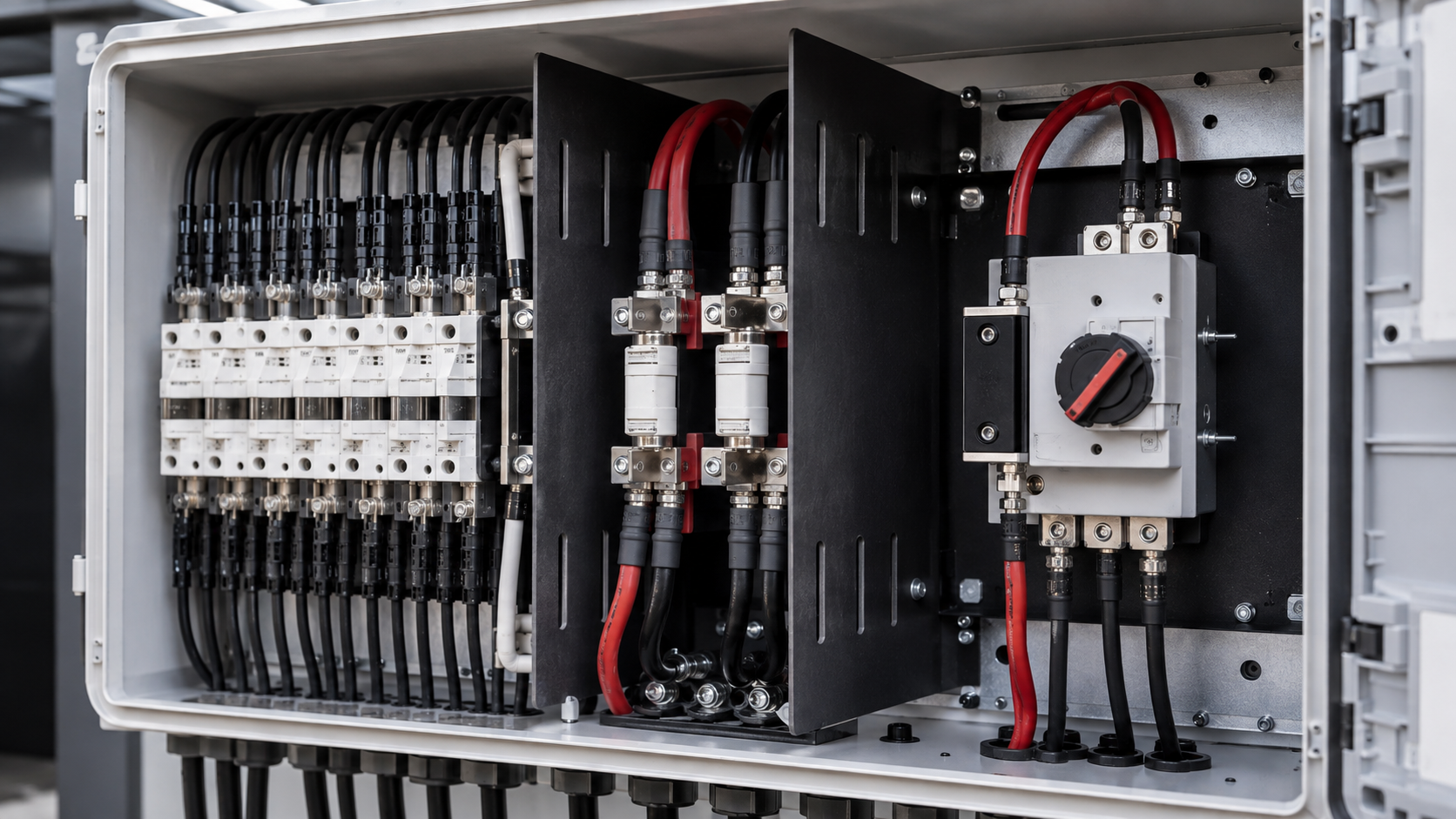
Why DC arcs are dangerous
A DC arc forms when current jumps a gap between conductors or between a conductor and earth. Because the DC voltage does not pass through zero, the arc sustains itself and can reach thousands of degrees, burning insulation, melting terminals and igniting nearby material. The risk grows with system voltage, which is why 1500 V arrays demand extra care.
- No natural current zero to self-extinguish the arc.
- Arc temperature can melt terminals and burn insulation.
- Higher system voltage increases the arc energy.
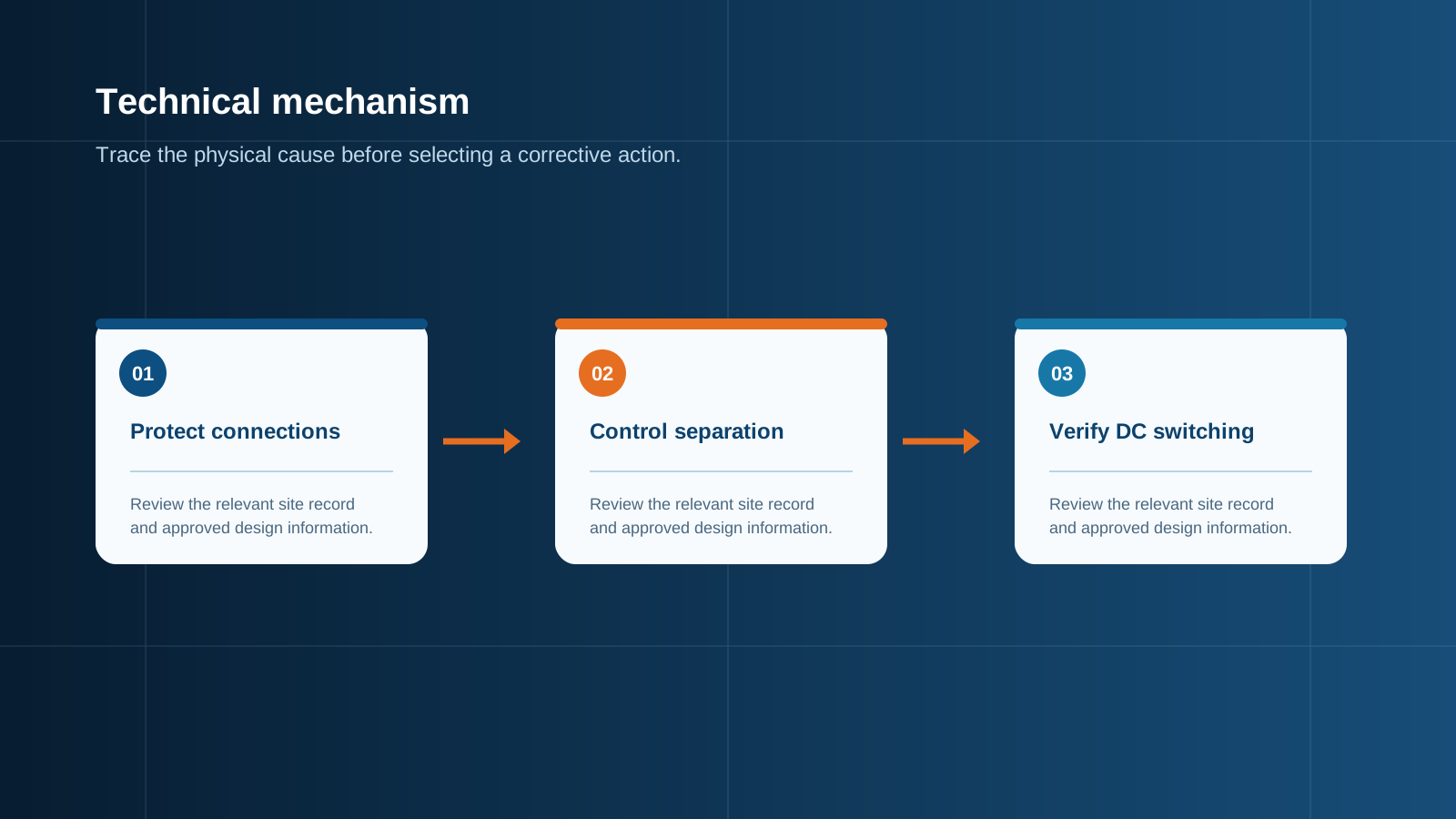
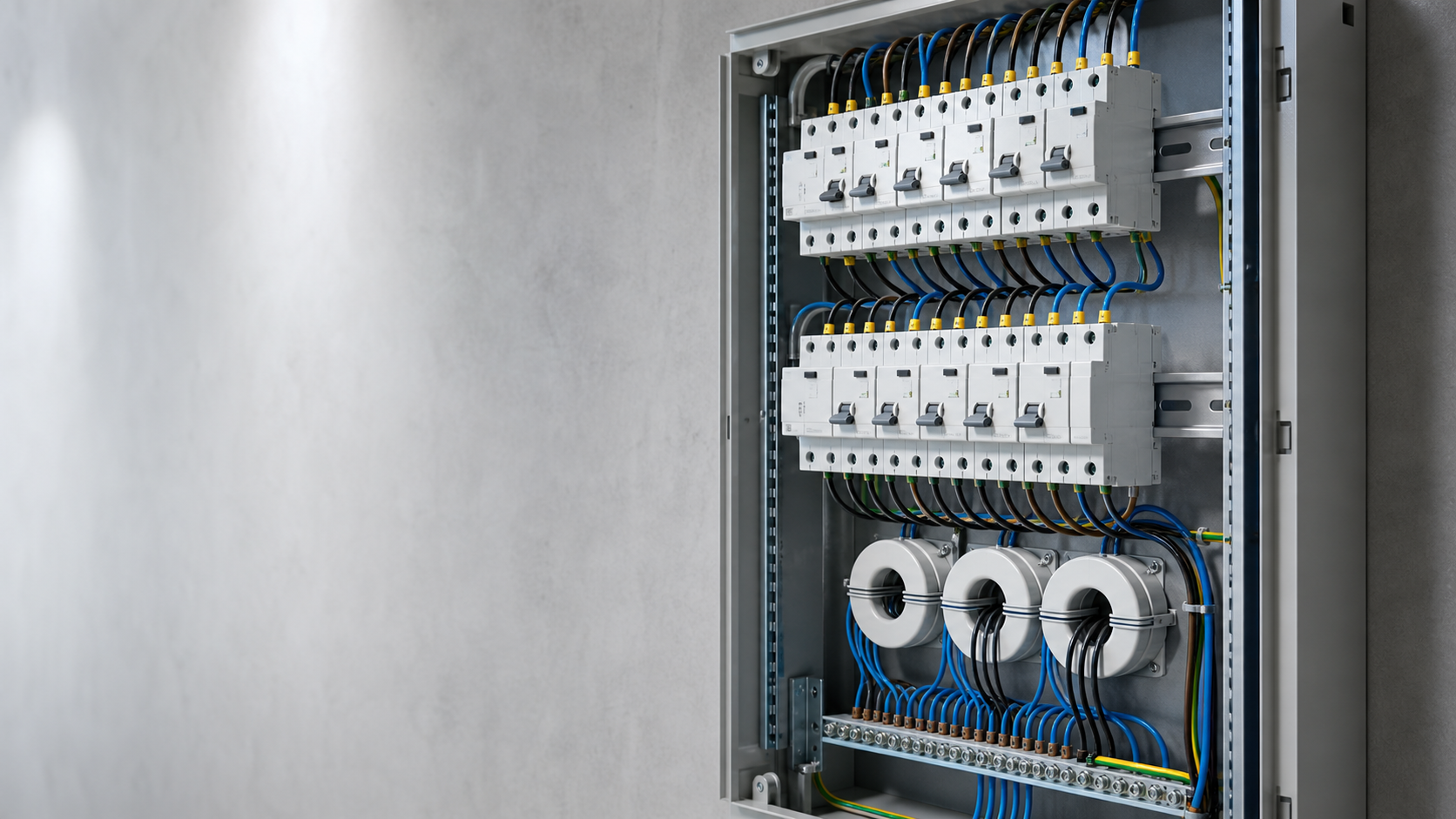
Technical diagram shown at a readable responsive scale.
Clearance and creepage
Clearance is the air distance between conductive parts; creepage is the distance along a surface. Both must be sized for the maximum system voltage plus transient margin so that a spark cannot bridge the gap. In a 1500 V combiner this drives the internal layout, barrier placement and component spacing.
- Size clearance for maximum system voltage and transients.
- Size creepage for pollution degree and surface track resistance.
- Use barriers where spacing alone is insufficient.
Terminal tightening
Loose terminals are a leading start point for arcs. A poor connection develops resistance, heats up, and the resulting hot spot can ionise the air and strike an arc. Correct torque at assembly, with a calibrated tool and a recorded value, is a simple and effective preventive step.
- Apply the specified torque with a calibrated tool.
- Record the torque value at assembly.
- Re-check after thermal cycling where required.
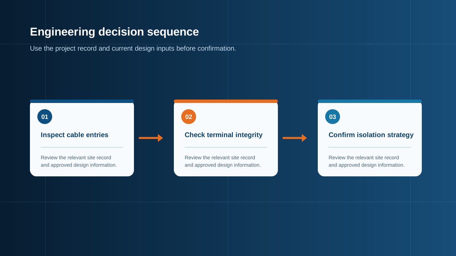
Technical diagram shown at a readable responsive scale.
Loose connection risk
A connection that loosens in service behaves like a partially open switch. Small movements generate intermittent contact, sparks and local heating, all of which can initiate an arc. Spring-loaded or twin-contact terminals reduce this risk, as does selecting hardware suited to thermal expansion.
- Intermittent contact sparks and heats locally.
- Spring or twin-contact terminals improve stability.
- Match hardware to the thermal cycle of the site.
Isolation and breaking
When an arc does occur, the combiner must be able to break the DC current safely. A DC-rated disconnect switch with certified breaking capacity interrupts the circuit, while the gPV fuse clears a dead short. Both are part of the arc-mitigation chain and must be rated for the system voltage and current.
- DC-rated disconnect with certified breaking capacity.
- gPV fuse clears the bolted fault quickly.
- Confirm ratings against system voltage and current.
The AFCI option
An arc-fault circuit interrupter (AFCI) detects the characteristic signature of a developing arc and opens the circuit before the fault escalates. In some markets AFCI protection is mandated for PV circuits. Where used, it complements, rather than replaces, good mechanical design.
- Detects the signature of a developing arc.
- Opens the circuit before escalation.
- Required in some regional PV wiring rules.
Enclosure design
The enclosure contributes to arc safety through material choice, ingress protection and internal segregation. A robust, non-combustible enclosure contains a small fault, while good ingress protection keeps dust and moisture, both of which lower creepage performance, away from the live parts.
- Use a robust, non-combustible enclosure.
- Keep dust and moisture out to protect creepage.
- Segregate high-voltage regions where needed.
Design rules summary
Arc prevention is a chain of small decisions: adequate clearance, correct torque, stable terminals, certified DC breaking, and AFCI where required. NEUTRON designs combiner boxes around these rules so the enclosure protects the array rather than becoming a fault origin.
- Size clearance and creepage for the system voltage.
- Torque and record every terminal.
- Rate isolation and breaking for DC duty.
This is general technical guidance. Confirm final ratings, protection coordination, installation and applicable local requirements against current standards, manufacturer documentation and the approved project design.
Frequently asked questions
Why are DC arcs more dangerous than AC arcs?
A DC circuit has no natural current zero, so once an arc strikes it can sustain itself and keep releasing heat until the circuit is isolated. AC arcs tend to extinguish at each current zero.
What role does clearance play in arc prevention?
Clearance is the air gap between live parts. Sizing it for the maximum system voltage plus transient margin stops a spark from bridging the gap and initiating an arc.
Why is terminal tightening important?
A loose terminal develops resistance and heats, and the hot spot can ionise air and start an arc. Correct torque with a calibrated tool removes that start point.
What is an AFCI and when is it used?
An arc-fault circuit interrupter detects the signature of a developing arc and opens the circuit before it escalates. It is required by some regional PV wiring rules and complements good mechanical design.
What are the key DC arc prevention design rules?
Size clearance and creepage for system voltage, torque and record every terminal, use stable terminals, fit DC-rated breaking, and add AFCI where the rule requires it.
Discuss your PV combiner requirement
Share the system voltage, string count, inverter interface and installation environment. NEUTRON can review the equipment configuration around your project documentation.
Discuss a projectContinue learning
Explore related technical guidance in Electrical Protection.

Published from the approved Period 09 source package. Technical values and final design decisions must be verified against the current applicable standard, manufacturer documentation and approved project design.