
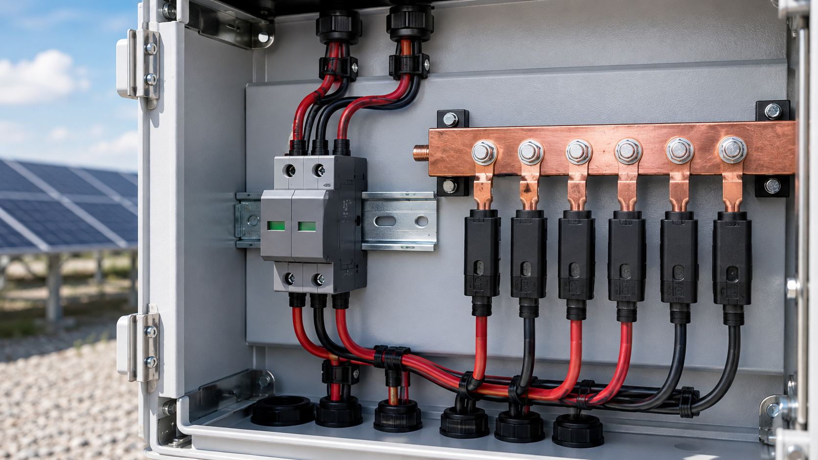
The physics: V equals L di/dt
During a surge the current changes extremely fast. The voltage dropped across a conductor is given by V = L multiplied by di/dt, where L is the lead inductance and di/dt is the rate of current change. A long lead has more inductance, so it develops a larger voltage during the event. That extra voltage adds to the SPDs rated protection level and reaches the equipment the SPD was meant to protect.
- V = L x di/dt describes the lead-induced voltage.
- Fast surges make di/dt very large.
- Extra lead voltage raises the voltage at the busbar.
Technical diagram shown at a readable responsive scale.
Why the 50 cm limit
Practical combiner layouts show that once the total lead length, counting both the pole conductor and the protective-earth return, grows past roughly 50 cm, the additional clamping voltage becomes significant relative to the equipment impulse withstand. Fifty centimetres is a field-proven compromise between installation freedom and protection quality. Shorter is always better.
- Total lead length near 50 cm keeps added voltage small.
- The limit covers both the pole and earth conductors.
- Shorter leads give better protection.
Measuring lead length
Lead length is measured along the conductor path, not as a straight-line distance. Include the routing through terminals, the bonding bar and any bend. Because the earth return counts too, the pole lead and the earth lead are added together to get the total that the 50 cm rule judges.
- Follow the actual conductor path, not the straight line.
- Add the pole lead and the earth lead together.
- Include terminal and bar entries in the measurement.
Technical diagram shown at a readable responsive scale.
Bends and impedance
A bend does not add much length, but a tight loop creates a larger loop area and more self-inductance and coupling. Keeping the leads straight, parallel and close together reduces the effective impedance. Avoid routing the SPD leads in a wide loop around other components.
- Keep leads straight and parallel.
- Avoid wide loops that raise self-inductance.
- Route close to the busbar.
SPD placement near the busbar
The simplest way to satisfy the rule is to mount the SPD directly beside the busbar it protects. A device placed far from the bar forces long leads no matter how neatly they are dressed. Good combiner layout reserves busbar space adjacent to the SPD position.
- Mount the SPD beside the protected busbar.
- Reserve adjacent busbar space in the layout.
- Minimise the run to the disconnect.
The grounding lead
The protective-earth lead is half of the total length budget, yet it is often the longer of the two. Connect it straight to the bonding bar with the shortest conductor practical, and never route it on a long detour. A thin or long earth lead is the usual cause of a failed lead-length check.
- Connect earth lead straight to the bonding bar.
- Keep it short and adequately sized.
- Do not detour the earth conductor.
Field failures
Many site failures trace back to a neatly installed but electrically long SPD. The device itself was correct, yet the busbar still saw an overvoltage because the leads were too long. The fault only appears after a real surge, which is why the rule must be checked at installation, not after an incident.
- Correct SPD, wrong lead length, still fails.
- Fault appears only during a real surge.
- Check at installation, not after.
Verification
Verification is straightforward: measure the total lead length along the path, confirm it is within the 50 cm budget, and record the value with the commissioning data. If the lead is too long, reposition the SPD or re-route the earth lead rather than accepting the excess.
- Measure total lead length along the path.
- Confirm within the 50 cm budget.
- Reposition the SPD if over budget.
This is general technical guidance. Confirm final ratings, protection coordination, installation and applicable local requirements against current standards, manufacturer documentation and the approved project design.
Frequently asked questions
Why is a 50 cm SPD lead length limit used?
Because lead inductance adds voltage during a surge through V = L di/dt. Past roughly 50 cm of total lead the extra clamping voltage becomes large enough to threaten the equipment impulse withstand, so the limit keeps protection effective.
What happens if the SPD lead is longer than 50 cm?
The added inductance raises the effective clamping voltage at the busbar, so the equipment may see a higher surge than the SPD rating suggests. Protection is partly defeated even with a correct device.
How do you measure SPD lead length?
Measure along the actual conductor path from the SPD to the busbar and to the bonding bar, including terminals, and add the pole lead and the earth lead together for the total.
Do bends in the SPD lead affect performance?
Bends add little length but a wide loop increases self-inductance and coupling. Keeping the leads straight, parallel and close to the busbar reduces impedance.
How is the 50 cm rule verified on site?
Measure the total lead length along the path at installation, confirm it is within budget, and record it with the commissioning data. Reposition or re-route if it exceeds the limit.
Discuss your PV combiner requirement
Share the system voltage, string count, inverter interface and installation environment. NEUTRON can review the equipment configuration around your project documentation.
Discuss a projectContinue learning
Explore related technical guidance in Electrical Protection.

Published from the approved Period 09 source package. Technical values and final design decisions must be verified against the current applicable standard, manufacturer documentation and approved project design.