
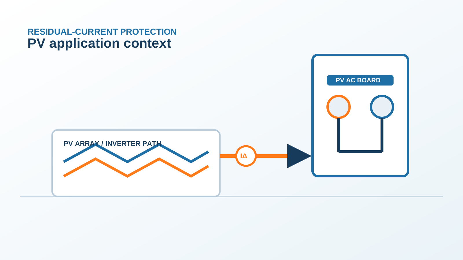
1. Thermal Versus Magnetic Elements
The thermal element reacts to sustained overcurrent and trips over seconds to minutes; the magnetic element reacts to a short circuit in milliseconds. Both must be rated for DC duty in a PV breaker.
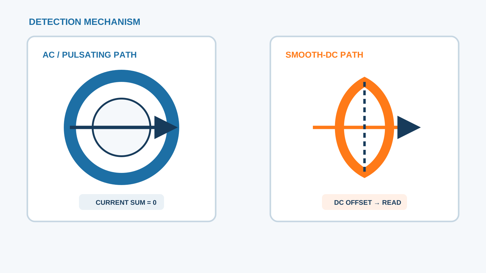
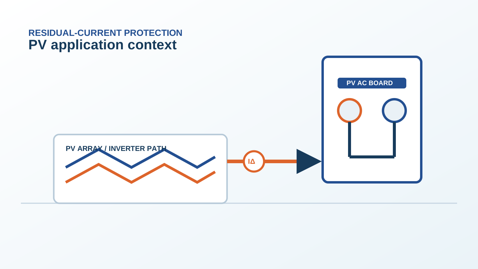
Technical diagram shown at a readable responsive scale.
2. PV Overload From Bifacial Gain
Bifacial modules can deliver more current than the front-side nameplate when rear irradiation is strong. A string that was sized to the front rating alone can sit in mild overload under real conditions.
3. Sizing to 1.25x Isc
Protection is set to at least 1.25 times the string short-circuit current so the device carries the peak including bifacial gain without tripping, while still clearing a true fault. This rule keeps the string online yet protected.
4. Thermal Trip Time at Overload
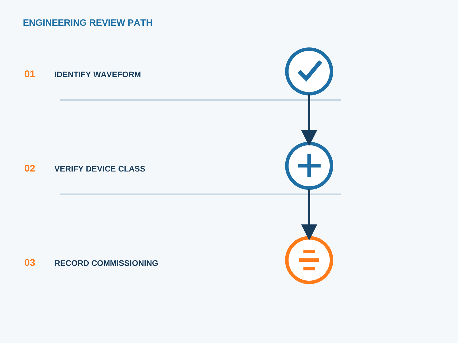
The thermal element trips faster as overload depth grows. A small excess above rating may take minutes, which is acceptable, while a large excess approaches the magnetic threshold.
5. Magnetic Element at Short Circuit
A hard short circuit drives the magnetic element instantly, independent of the thermal state. The DC breaking capacity then decides whether the arc is cleared.
6. Ambient Temperature Effect
High ambient temperature shifts the thermal calibration, so a breaker in a hot enclosure may trip earlier. The derating must be applied to the trip setting, not only the current rating.
7. Coordination With Fuse
Where a string fuse sits upstream, the MCB thermal and magnetic bands should sit below the fuse curve so the nearest device acts first. Selectivity keeps the fault local.
8. Field Setting Practice
Set the rating from the measured Isc with bifacial gain, apply ambient derating, and record it. NEUTRON supplies DC-rated thermal-magnetic breakers verified for PV string duty.
This is general application guidance. Confirm final ratings, trip settings, standards, inverter instructions and local installation requirements against approved project documentation and a qualified engineer's review.
Frequently asked questions
How does a DC MCB trip on overload?
The thermal element heats with sustained overcurrent and opens the contacts after a time set by the overload depth.
Why size to 1.25x Isc?
It lets the device carry the peak string current including bifacial gain without nuisance tripping, while still clearing faults.
Does heat slow the trip?
High ambient can shift calibration so the device trips earlier; the setting must be derated for temperature.
MCB or fuse for overload?
An MCB gives resettable thermal-magnetic protection; a gPV fuse is the upstream back-up. The two are coordinated, not used as substitutes.
Bring the protection inputs to the first review.
Set the rating from the measured Isc with bifacial gain, apply ambient derating, and record it. NEUTRON supplies DC-rated thermal-magnetic breakers verified for PV string duty.
Discuss a project requirementContinue learning
Explore related technical guidance in Electrical Protection.

Published from the approved period 10 source package; technical claims and source wording are retained for review.