
1. Solar and storage on one site
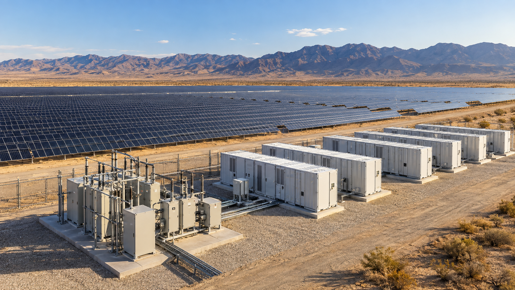
A second-phase Benban development pairs about 1 GW of PV with a large battery energy storage system. Co-locating storage with PV means the protection and switching equipment must suit a variable renewable input and a battery that charges and discharges. Availability and clean isolation matter for both.
2. NEUTRON DC protection scope
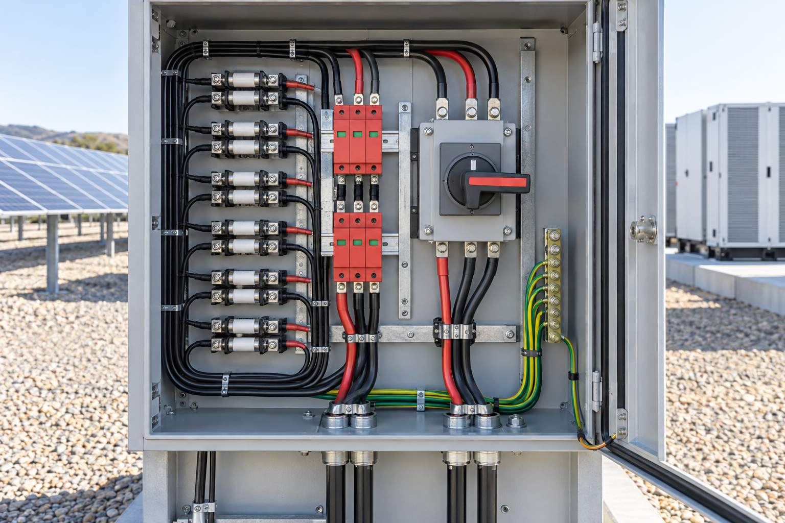
- PV combiner boxes rated to 1500 V DC with individual gPV fuse protection.
- DC disconnect switches and Type 2 DC SPDs staged to the 1500 V envelope.
- DC MCBs for auxiliary and monitoring circuits.
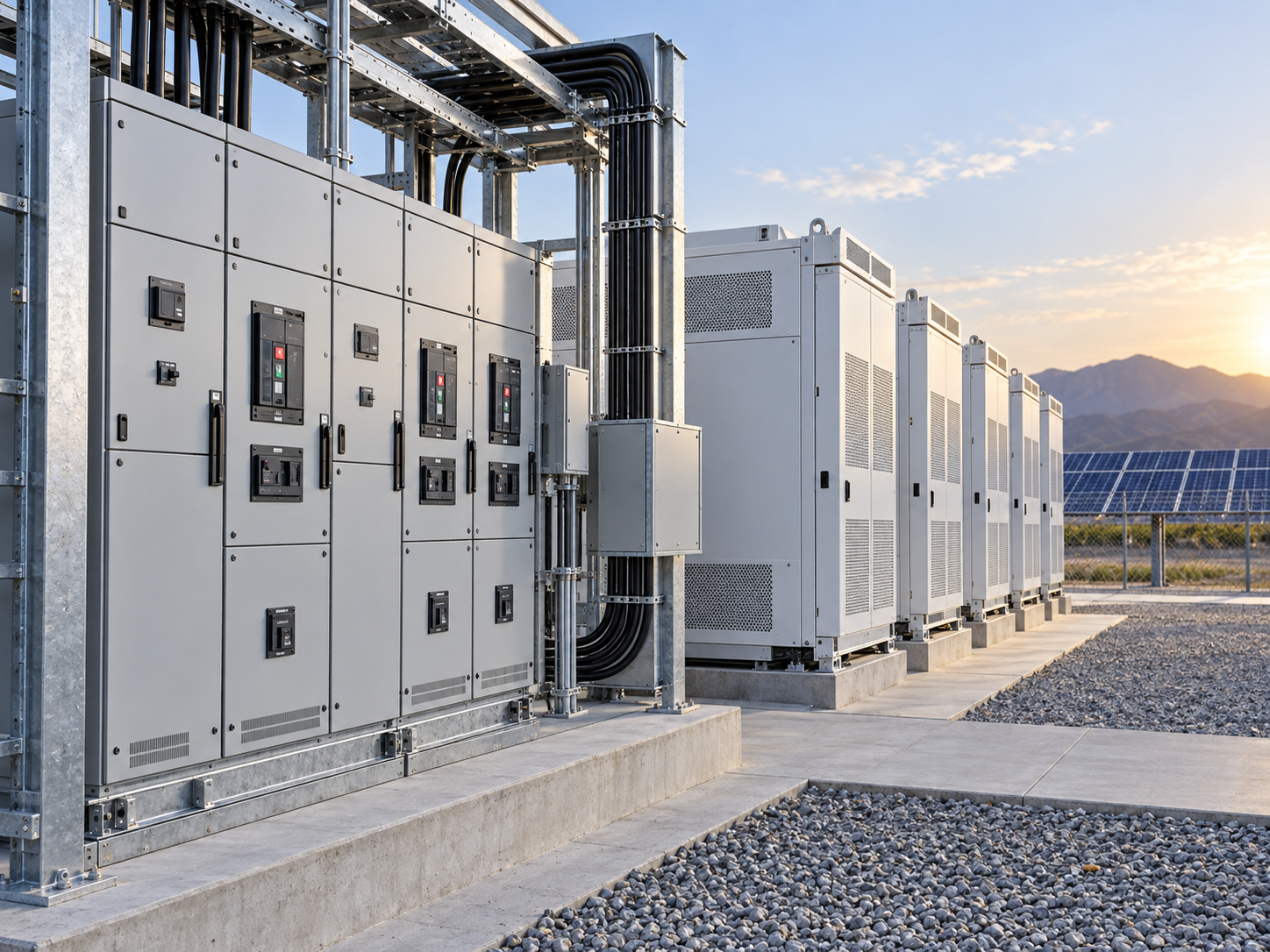
- Low-voltage switchgear for the AC collection side.
3. Coordination with EPC-supplied storage
NEUTRON did not supply the batteries or inverters. The protection scope was coordinated to the EPC ratings: combiner and DC fuse limits matched to the array the inverter expects, and the AC board sized to the inverter output and priority loads.
4. Selective protection
- gPV fuses and downstream devices coordinated so a fault clears at the nearest point.
- Spare fuses and labelled boards for quick restoration.
- Monitoring for early fault detection.
5. Outcome
The protection layer gave the PV side a serviceable foundation alongside the storage system. The lesson is that PV-plus-storage needs the same DC discipline, plus tighter coordination with the EPC equipment.
Final ratings, coordination, installation and applicable local requirements must be verified against current standards, manufacturer documentation and the approved project design.
Frequently asked questions
How does PV plus storage change protection?
The solar side still needs full DC discipline; the protection layer is coordinated to the EPC battery and inverter ratings.
What does NEUTRON supply?
PV combiner boxes, DC disconnect and SPD, DC MCBs and low-voltage switchgear; batteries and inverters are integrated by others.
Which standards apply?
IEC 62916, IEC 60269-6, IEC 60947-2, IEC 61643-31, IEC 61439 and IEC 62271.
Why coordinate with the EPC equipment?
Matching combiner and fuse limits to the array the inverter expects keeps the protection layer consistent and serviceable.
Review the PV and storage interfaces together.
Share the PV collection, inverter output and priority-load inputs for coordinated scope review.
Discuss a projectContinue learning
Explore related technical guidance in Power Distribution.

Published from the approved Period 12 source package; project, technical and standards statements are retained from the supplied publication content.