
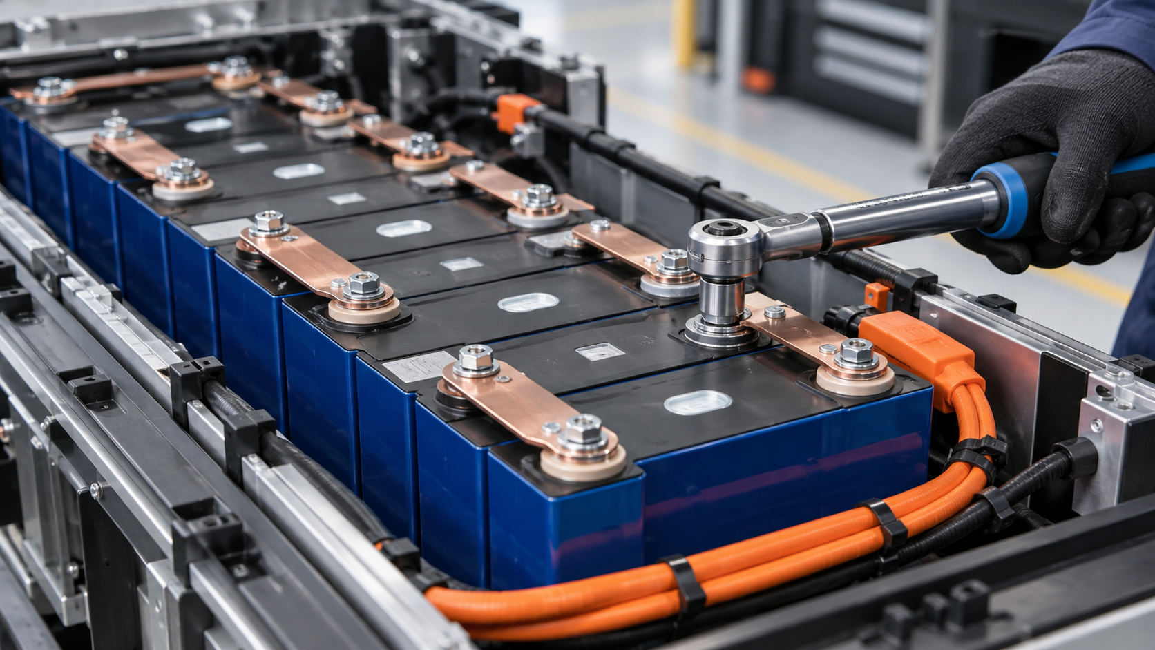
Prismatic LiFePO4 terminal types
Large-format prismatic cells arrive with one of a few terminal styles, and each demands a different assembly technique. Identifying the style before ordering hardware avoids the most common integration delay.
Aluminium terminals matter more than most integrators expect. Aluminium creeps under sustained load, forms an insulating oxide within seconds of being cleaned, and has a thermal expansion coefficient different from copper. Every torque and busbar decision that follows is shaped by those three facts.
- Threaded blind hole in an aluminium terminal, usually M6 or M8, taking a bolt from above; the thread depth is shallow and easily stripped.
- Protruding threaded stud with a nut, more tolerant of repeated assembly but requiring careful control of stack height.
- Flat welded tab intended for laser or ultrasonic welding, typical of factory-assembled modules and not intended for field bolting.
- Copper-clad or nickel-plated aluminium terminals, which change the contact metallurgy and therefore the preferred busbar material and coating.
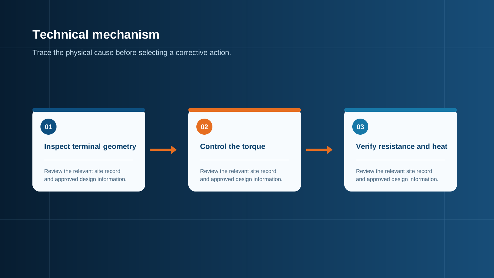
Technical diagram shown at a readable responsive scale.
M4 to M8 torque specifications and why they matter
The cell manufacturer datasheet is always the governing document, but the values used across the industry fall into a narrow band. Typical figures are roughly 2 N·m for M4, 4 N·m for M5, 5 to 6 N·m for M6, and 8 to 12 N·m for M8 threads into aluminium terminals.
Too little torque leaves insufficient contact pressure, so the real contact area shrinks to a few microscopic points and joint resistance climbs. Too much torque strips the shallow aluminium thread or deforms the terminal, which is unrecoverable in the field. Both failure modes end the same way — a hot joint that degrades further each cycle, because higher resistance produces more heat, and heat accelerates relaxation of the joint.
Measuring internal resistance
Cell internal resistance is measured with a four-wire alternating-current milliohm meter, conventionally at 1 kHz. A healthy large-format lithium iron phosphate cell typically reads well under one milliohm, and the important figure is consistency across the bank rather than the absolute value.
A practical acceptance rule is to reject or segregate any cell whose resistance deviates by more than about 20% from the batch average, because that cell will run hotter and age faster than its neighbours in a series string. Record every reading at commissioning so later measurements have a baseline; resistance that has risen materially against the commissioning record usually indicates a joint problem rather than cell degradation.
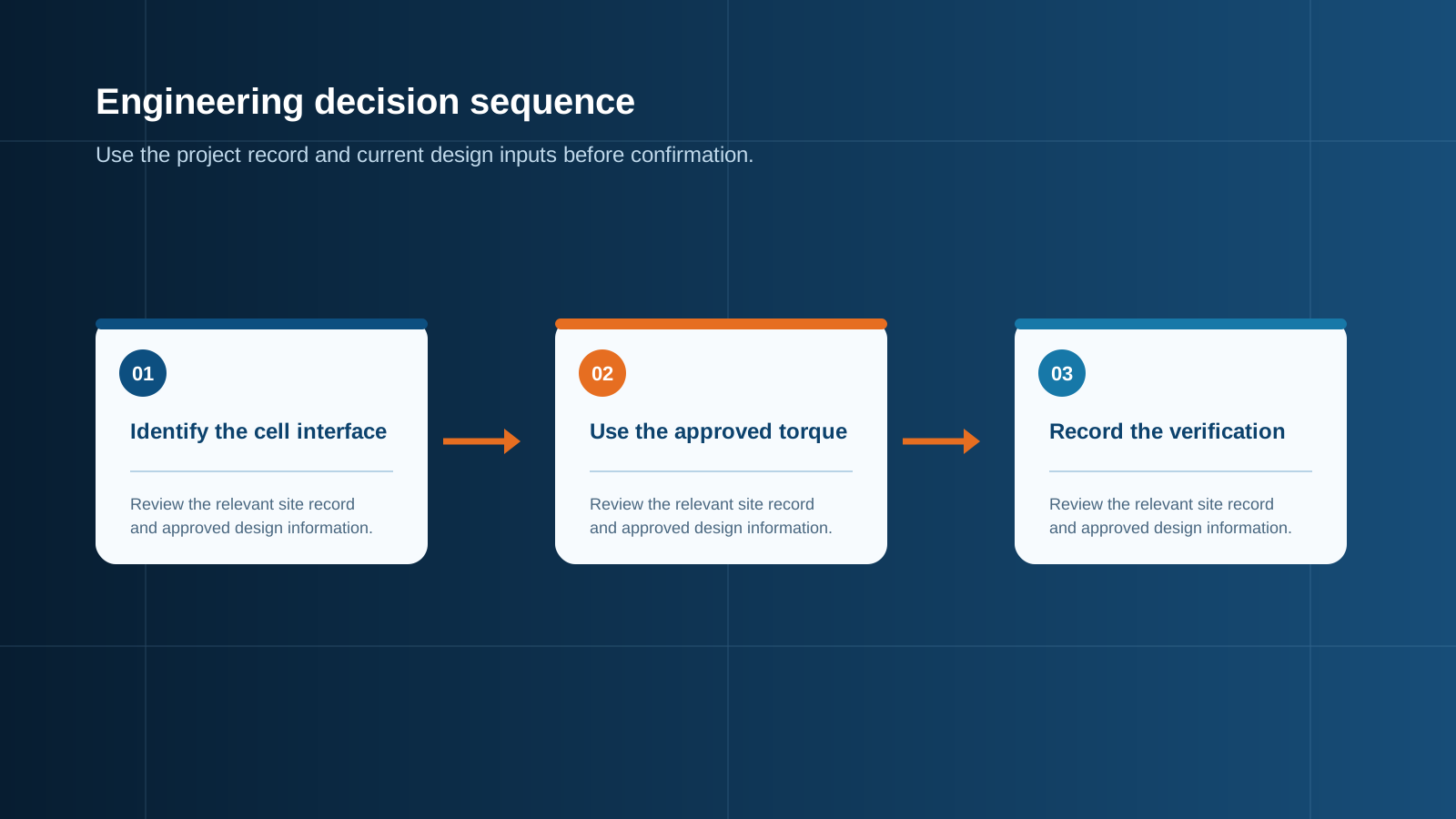
Technical diagram shown at a readable responsive scale.
Busbar and connection best practice
The busbar is a precision part, not a strap. Its job is to carry high continuous current between terminals without imposing mechanical stress on them, and a well-made copper bar contributes almost nothing to total bank resistance if it is prepared correctly.
- Match the bar cross-section to the continuous bank current with a comfortable temperature-rise margin, and never rely on peak-rated figures for a continuous duty.
- Tin-plate or nickel-plate copper bars where they meet aluminium terminals to limit galvanic attack and oxide growth at the interface.
- Clean and flatten contact faces immediately before assembly; an oxide film formed in minutes can multiply joint resistance.
- Use a flexible or laminated bar between cell groups so that expansion, swelling and vibration are absorbed by the conductor rather than the terminal thread.
- Fit a spring or conical washer under the bolt head to maintain contact pressure as aluminium relaxes over the first weeks of service.
- Never sandwich a sense wire directly under the main busbar; give voltage-sensing leads their own dedicated screw or terminal position.
Thermal rise at the terminal
Joint dissipation follows the square of current multiplied by resistance, so small resistance errors release a great deal of heat at high current. A 100 A bank current through a joint that should read 50 microhms but actually reads 500 microhms turns half a watt into five watts at a single small metal interface.
Thermal imaging during a commissioning discharge is the fastest way to find these defects. Any terminal running more than a few degrees above the bank average deserves investigation, and a joint that is markedly hotter than its neighbours should be dismantled, cleaned and retorqued rather than simply tightened further.
Protection between cells and BOS
A battery bank is a low-impedance direct-current input with an extremely high prospective fault current, which places demands on the protection devices that no photovoltaic string imposes. Cell-level connection quality is only half the safety story; the boundary between the bank and the rest of the installation carries the other half.
- A direct-current isolator rated for the bank voltage and capable of interrupting its prospective fault current, positioned so the bank can be worked on safely.
- Overcurrent protection with a direct-current breaking capacity that genuinely covers the bank short-circuit contribution, not an alternating-current rating reused by assumption.
- Surge protection on the conductors that leave the enclosure, coordinated with the array-side stages.
- Clear separation and labelling of the management-system sense wiring from power conductors, so a maintenance error cannot short a cell group through a signal lead.
Torque verification in the field
Verification is a documented procedure, not a spot check. Use a calibrated torque wrench, work in a defined sequence so no joint is missed, and record the value applied at every position. Where the cell manufacturer specifies it, retorque after the first few thermal cycles because aluminium relaxes measurably in early service.
Two habits prevent most warranty disputes: mark each completed joint with a paint or lacquer witness line so movement is visible at a glance, and repeat the milliohm measurement across each joint after tightening. A joint that reads high after correct torque has a surface preparation problem that no additional force will fix.
Integration with energy-storage control
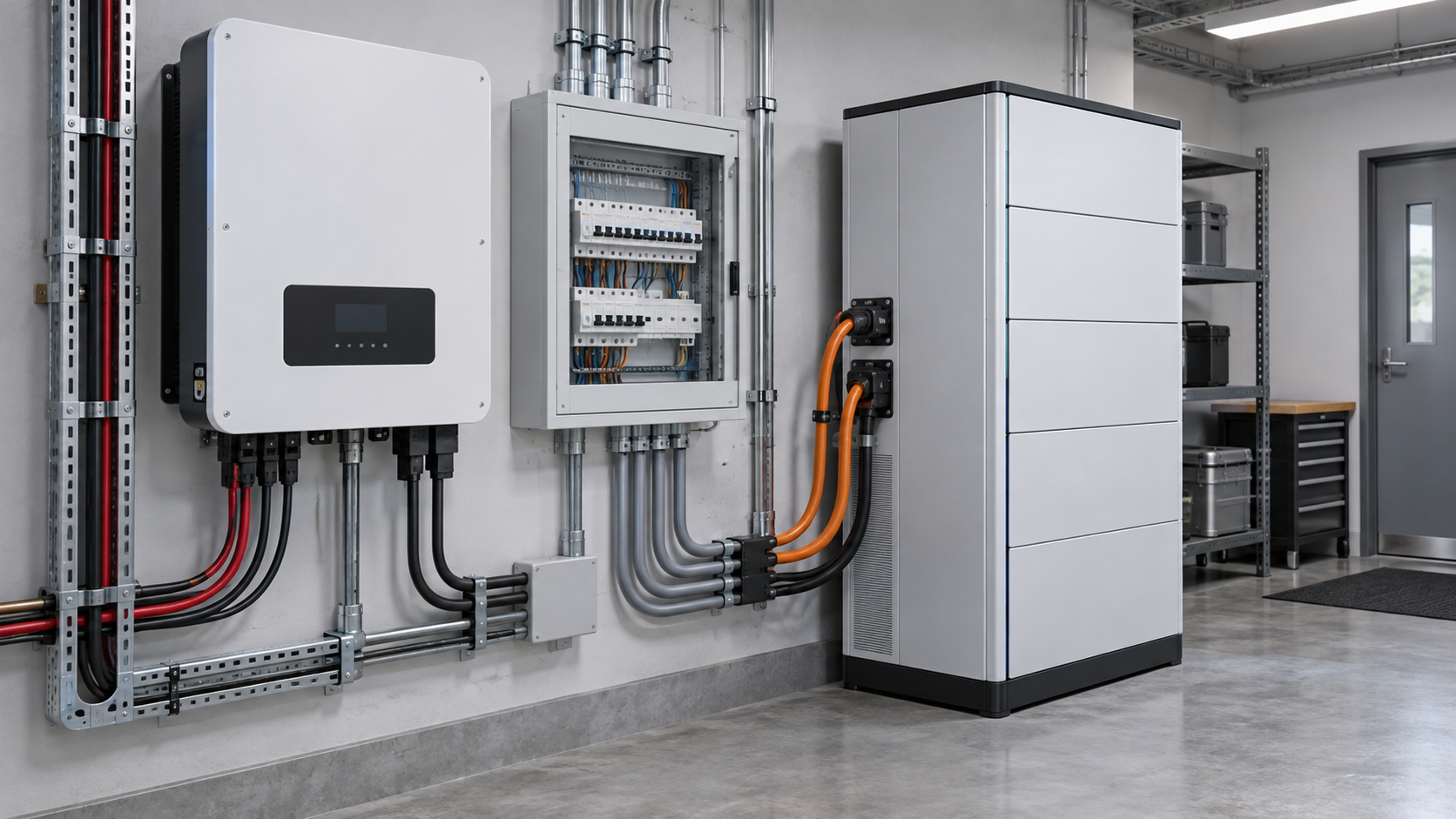
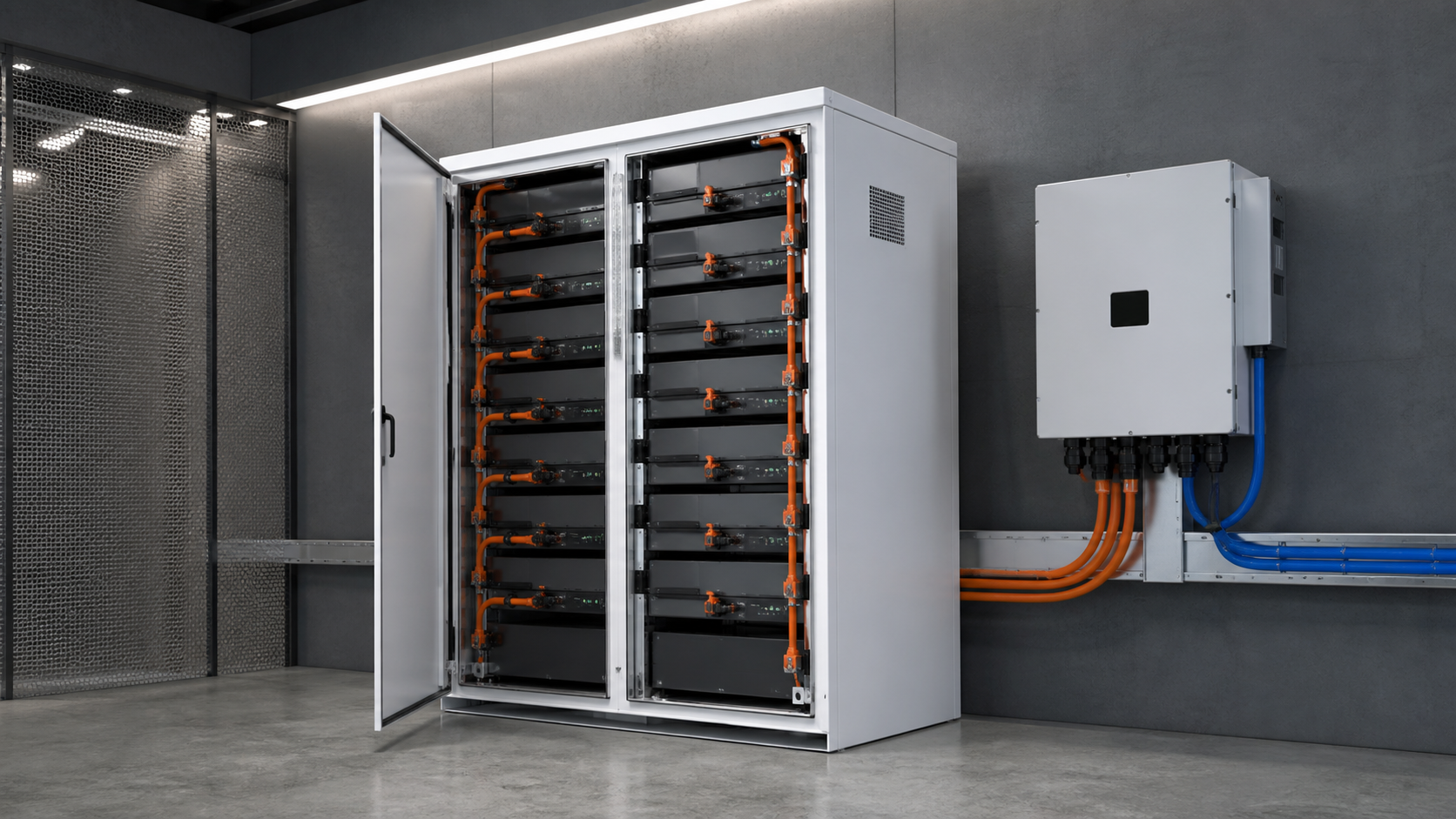
Once the cells are assembled and verified, the bank still needs a controlled electrical boundary. An energy-storage control cabinet provides that boundary: isolation, overcurrent protection, surge protection, metering and the switching interface between the battery system and the array or distribution board.
Sizing it correctly requires the bank nominal and maximum voltage, the continuous and peak current, the prospective fault current and the coupling arrangement on the direct-current or alternating-current side. NEUTRON reviews those figures and prepares a cabinet and busbar configuration to match, so the connection quality achieved at the cells is preserved all the way to the system boundary.
This is general technical guidance. Confirm final ratings, protection coordination, installation and applicable local requirements against current standards, manufacturer documentation and the approved project design.
Frequently asked questions
What torque for M6 LiFePO4 terminals?
Most large-format prismatic cells specify roughly 5 to 6 N·m for an M6 thread in an aluminium terminal, but the cell datasheet always takes precedence because thread depth and terminal alloy vary between designs.
How do cells connect to busbar?
Through bolted copper busbar with plated contact faces, tightened to the cell manufacturer torque value with a spring or conical washer to hold contact pressure as aluminium relaxes. Contact faces must be flat and cleaned immediately before assembly.
Discuss your PV requirement
Share the system voltage, string arrangement, inverter interface and installation environment. NEUTRON can review the equipment configuration around your project documentation.
Discuss a projectContinue learning
Explore related technical guidance in Solar PV.

Published from the approved Period 06 source package. Technical values and final design decisions must be verified against the current applicable standard, manufacturer documentation and approved project design.