
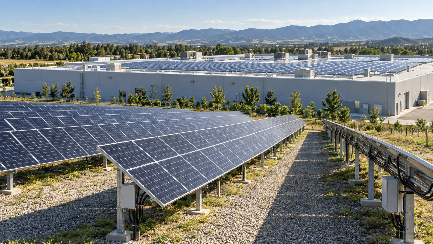
Two mounting worlds
A rooftop system uses an existing structure. The roof provides the load-bearing surface, the orientation, and often the tilt, so the array must accept whatever geometry the building offers. Modules are typically laid out in irregular blocks around obstructions such as vents, dormers, skylights and parapets, and the electrical room or inverter location is usually already fixed by the building layout.
A ground-mounted system starts from a blank field. Racking is designed rather than inherited, so tilt and azimuth can be optimised, row pitch can be selected to control inter-row shading, and the array can be laid out in long uniform rows. The trade-off is that the ground array needs foundations, perimeter security, access roads or paths, and a longer route back to the point of interconnection.
- Rooftop: fixed geometry, zero land cost, short cable runs, restricted access.
- Ground mount: optimised geometry, land and civil cost, long cable runs, easy access.
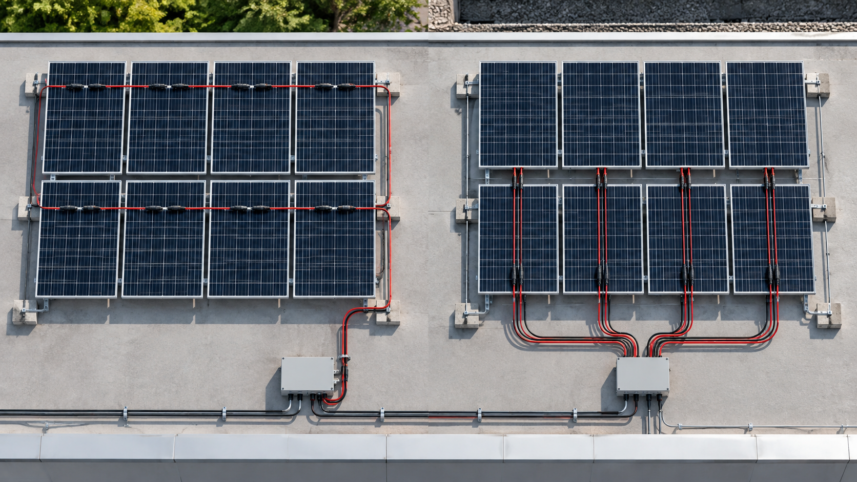
- Rooftop: array is fragmented into several small sub-arrays; ground mount: array is regular and repeatable.
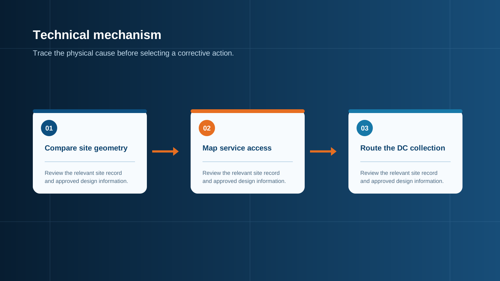
Technical diagram shown at a readable responsive scale.
Cost comparison
On a per-watt basis, small rooftop systems are usually cheaper to install because there is no land preparation, no foundation work and no trenching. The structure already exists and the run from array to inverter is short. As capacity grows, however, the balance shifts. Ground-mounted arrays benefit strongly from repetition: the same racking assembly, the same string length and the same combiner configuration are replicated across the field, which drives down labour cost per watt.
The hidden cost items differ as well. Rooftop work carries roof penetration, waterproofing, fall protection and access constraints, and any future roof replacement means removing and reinstalling the array. Ground mount carries civil works, fencing, cable trenching and often a longer medium-voltage or low-voltage feeder. Beyond a few hundred kilowatts the field layout normally wins on total installed cost, while below that threshold the roof is generally more economical if the structure is sound.
Yield and shading differences
Ground-mounted arrays usually generate more per installed kilowatt. Tilt and azimuth can be set to the optimum for the latitude, row spacing can be chosen to limit self-shading, and the modules sit in free air so the rear surface runs cooler, which lifts output through the temperature coefficient. Where bifacial modules are used, elevated ground mounting on a reflective surface adds rear-side gain that a flush rooftop installation cannot achieve.
Rooftop arrays are constrained to the roof plane and are far more exposed to localised shade from chimneys, plant rooms, adjacent buildings and trees. Because a shaded cell forces the bypass diode to conduct and drags down the whole series string, roof shading tends to cause disproportionate losses. The practical consequence is that rooftop layouts often need more sub-arrays with shorter strings, or module-level electronics, whereas ground arrays can run long uniform strings with predictable behaviour.
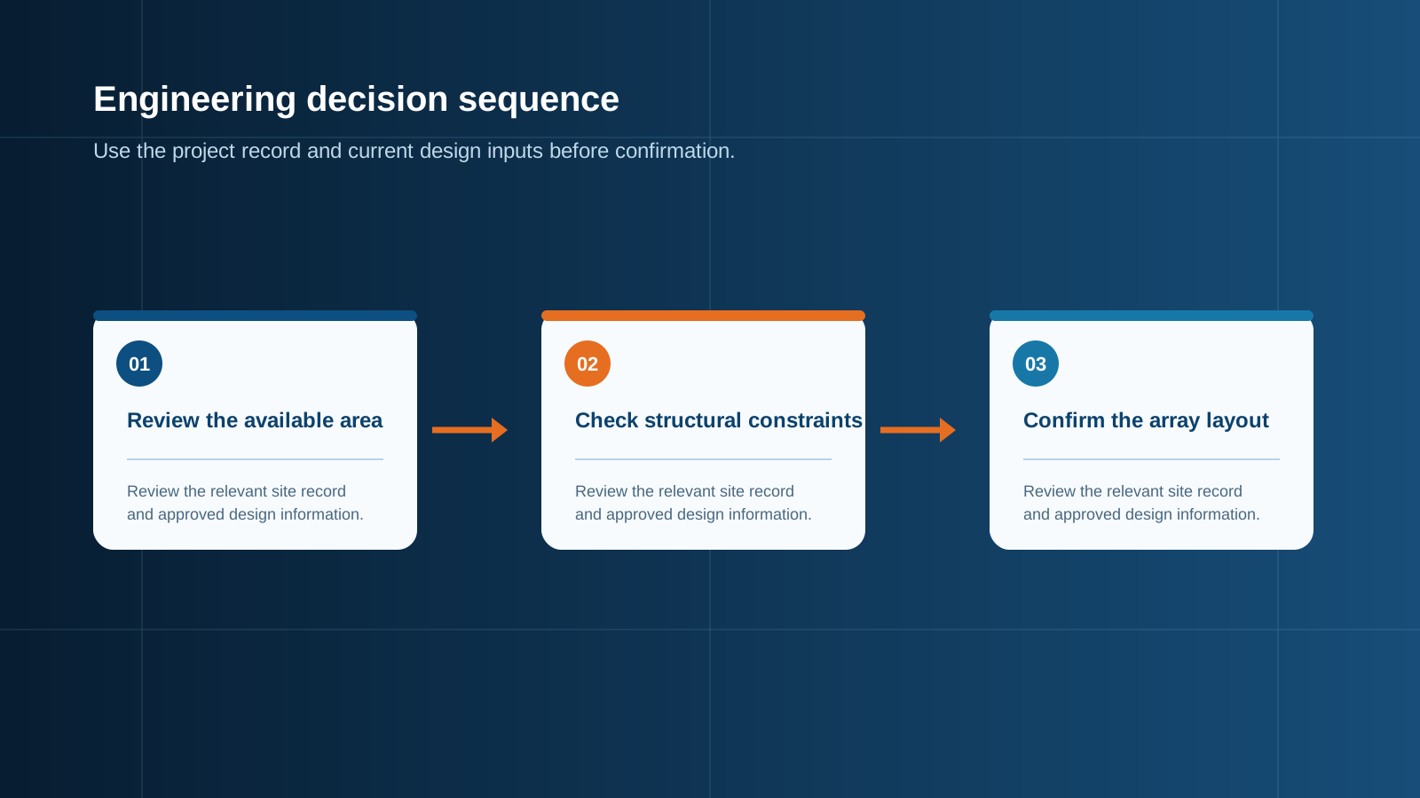
Technical diagram shown at a readable responsive scale.
String sizing for each layout
String sizing follows the same rules in both cases: the cold-weather open-circuit voltage of the series string must stay below the maximum system voltage and below the inverter input ceiling, while the warm-weather maximum-power voltage must remain inside the tracking window. What differs is how much freedom the designer has to reach the ideal string length.
More strings mean more fused inputs, more terminals and a physically larger combining enclosure, so the mounting decision feeds directly into the input count you specify.
- Ground mount: uniform rows allow the string to be sized to the electrical optimum, typically the maximum permitted series count, which reduces the number of strings and therefore the number of protected inputs.
- Rooftop: usable roof planes rarely divide evenly into the ideal series count, so strings are often shorter and more numerous, and mixed orientations may require separate tracking inputs.
- Both: verify the series count against the lowest expected ambient temperature at the site, not the annual average, because open-circuit voltage rises as temperature falls.
Voltage drop and cable runs
Cable length is the single biggest electrical difference between the two layouts. A rooftop string may reach its combining point in fifteen to thirty metres, while a ground array can easily require one hundred metres or more from the far row back to the collection point. Because direct-current voltage drop is proportional to conductor length and current, and inversely proportional to cross-section, long runs either need a larger conductor or must be run at higher string voltage.
The usual practice is to keep total direct-current loss on the array side within roughly one to two percent of the operating voltage. Two levers control this: raise the string voltage by using the longest permitted series count, which lowers current for the same power, and increase the conductor cross-section on the longest runs. Sizing every run to the worst-case row rather than the average row avoids a situation where the most distant string quietly underperforms for the life of the plant.
Combiner box placement
In a rooftop system the combiner box is usually mounted close to the inverter, in a plant room or on a wall near the point of interconnection, because the string runs are short and roof space is at a premium. Access for maintenance is often the limiting factor, and enclosures are frequently specified for indoor or sheltered mounting.
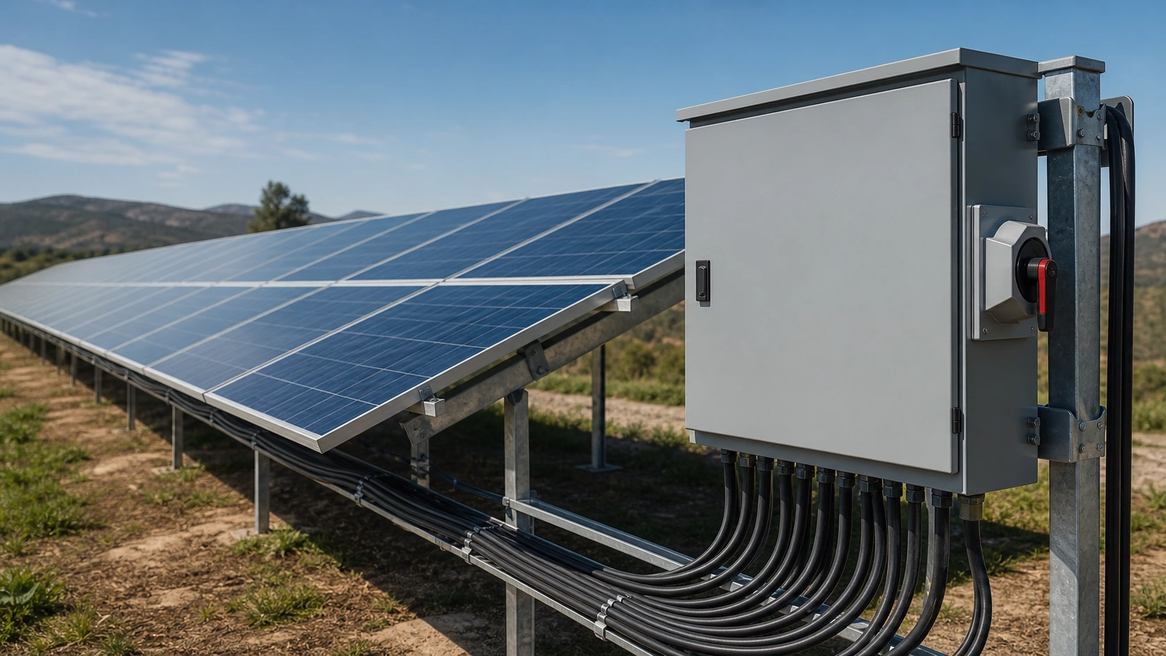
In a ground-mounted plant the combining equipment is pushed out into the field, positioned near the centre of the block it serves so that string cables stay short and only one larger output cable runs back to the inverter station. This changes the enclosure specification substantially: the box is fully exposed, needs a high ingress protection rating, ultraviolet-stable finish and a corrosion class appropriate to the environment, and must handle a wide daily temperature swing. The internal busbar also carries the aggregated current of every string in the block, so its continuous rating and terminal torque become critical.
Protection and isolation
Both layouts require the same protective functions, but the priorities shift. Every string needs dedicated overcurrent protection sized to its short-circuit current, and every sub-array needs a load-break isolation device so the array can be safely worked on. Surge protection is required on the direct-current side in both cases, and coordinated on the alternating-current side after the inverter.
For projects where a distribution assembly is also required, the collection point can be combined with low-voltage switchgear so that string protection, isolation, surge protection and outgoing feeders sit in one coordinated set of equipment.
- Ground mount: larger exposed area and long conductor loops raise induced surge energy, so a robust direct-current surge protective device close to the combining point is essential, and earthing of racking and enclosures must be continuous.
- Rooftop: the building's own lightning protection and earthing system must be coordinated with the array, and the isolation point should be reachable without working at height.
- Both: label every string, fit a clearly identified direct-current disconnect, and coordinate the string overcurrent device with the downstream alternating-current breaker.
Which fits your site
If the roof is structurally sound, correctly oriented and shade-free, and the required capacity fits within the available plane, rooftop mounting is usually the faster and cheaper route with the shortest cable runs and the simplest protection scheme. If land is available, the capacity is larger, or the roof is fragmented, heavily shaded or nearing the end of its service life, ground mounting will deliver more energy per installed kilowatt and a cleaner, more repeatable electrical layout.
Whichever route you take, the decision should be made before the electrical equipment is specified, because it determines string count, conductor size, enclosure environmental rating and busbar current. NEUTRON reviews the array layout and site conditions and prepares a configuration discussion for the combining and protection equipment that matches it.
This is general technical guidance. Confirm final ratings, protection coordination, installation and applicable local requirements against current standards, manufacturer documentation and the approved project design.
Frequently asked questions
Is ground mount cheaper than rooftop?
For small systems, rooftop is usually cheaper because there is no land preparation, no foundation work and no trenching, and the run from array to inverter is short. Ground mounting adds civil cost that a roof simply does not have.
Which yields more?
Ground-mounted arrays generally yield more per installed kilowatt. Tilt and azimuth can be optimised, row pitch can be set to limit self-shading, and free air circulation around the modules keeps cell temperature lower, which improves output through the temperature coefficient.
Discuss your PV requirement
Share the system voltage, string arrangement, inverter interface and installation environment. NEUTRON can review the equipment configuration around your project documentation.
Discuss a projectContinue learning
Explore related technical guidance in Solar PV.

Published from the approved Period 06 source package. Technical values and final design decisions must be verified against the current applicable standard, manufacturer documentation and approved project design.