
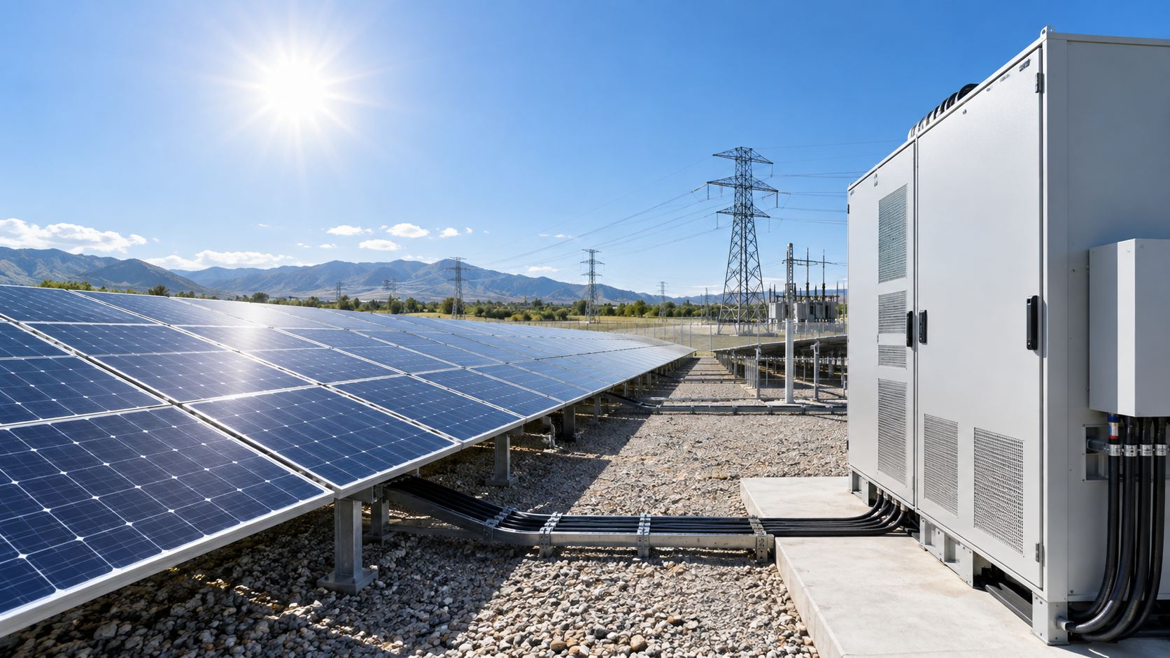
What inverter clipping means
Clipping occurs when the direct-current power arriving from the array exceeds what the inverter is rated to convert. The inverter does not fail or overheat; it simply moves its operating point away from the maximum power point until the input power matches the output limit it can deliver. The excess is never generated in the first place, so nothing is dissipated as heat inside the equipment.
Visually the effect is a plateau across the middle of the day. The peak looks trimmed, which is where the term comes from. What matters commercially is not the height of the plateau but its area: how many kilowatt-hours across the year fall above the conversion ceiling.
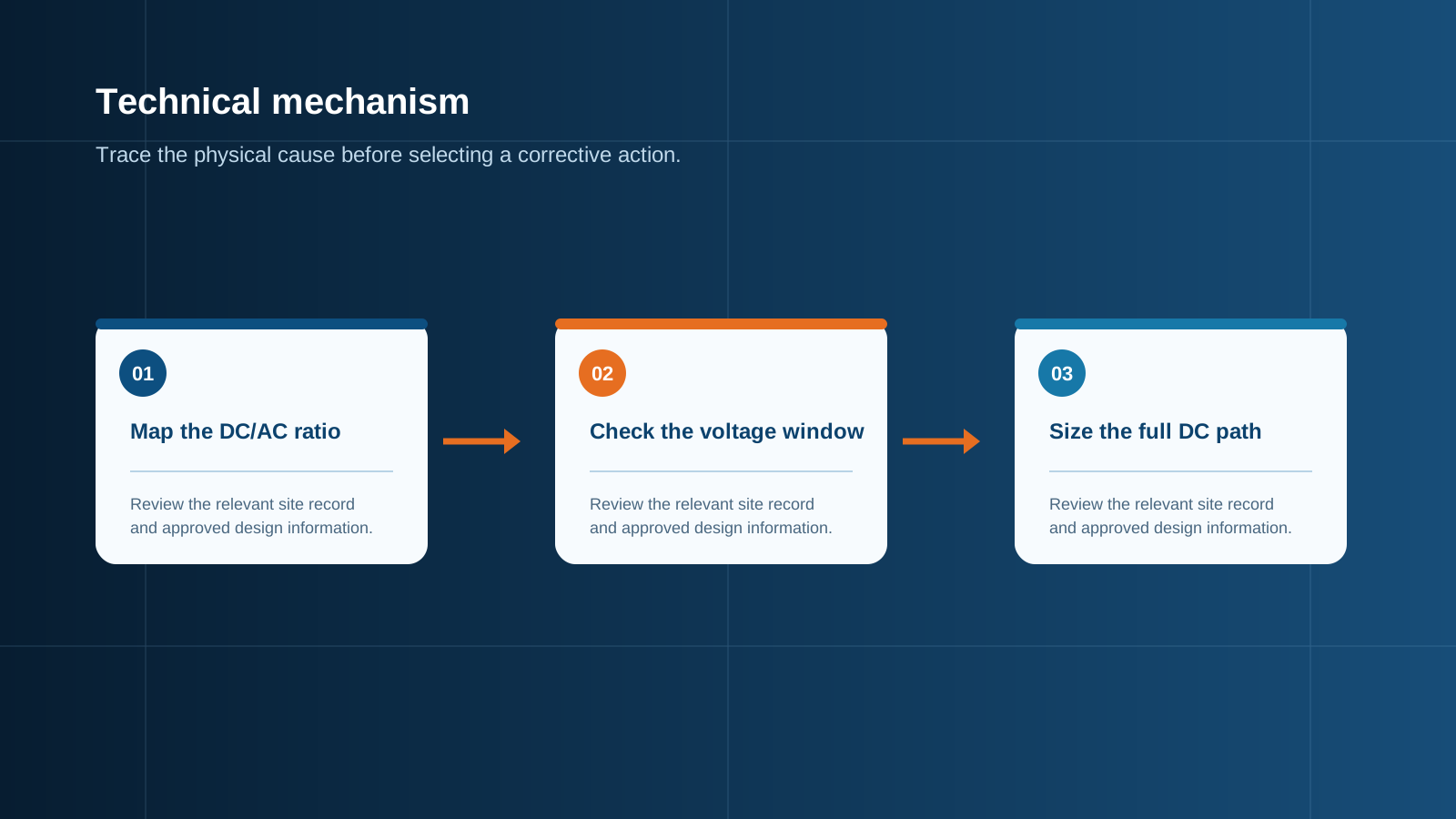
Technical diagram shown at a readable responsive scale.
DC/AC ratio and why it drives clipping
The DC/AC ratio is the installed array capacity at standard test conditions divided by the rated alternating-current capacity of the inverter. A 12 kWp array on a 10 kW inverter gives a ratio of 1.2. Because an array almost never reaches its nameplate value in the field, a ratio above 1.0 is normal engineering practice rather than an error.
Three factors decide how much of the year sits above the ceiling:
- Irradiance profile — clear desert sites spend more hours near full output than cloudy maritime climates.
- Cell temperature — hot arrays lose several percent of nameplate power, pulling the curve down under the ceiling.
- Orientation — an east-west split spreads generation across the day and flattens the peak naturally, so clipping starts at a higher ratio.
Annual loss by ratio band
Loss does not rise linearly. It stays negligible while the array only briefly touches the ceiling, then accelerates once a wide band of midday hours is capped. The bands below are typical for a well-oriented fixed-tilt array in a moderate climate and should be confirmed with site-specific modelling.
- Ratio 1.0 to 1.15 — clipping is effectively zero; the inverter is under-used most of the year.
- Ratio 1.15 to 1.30 — annual loss typically stays below 1%, and specific yield per kilowatt of inverter improves.
- Ratio 1.30 to 1.50 — annual loss of roughly 1% to 3%, still usually outweighed by the extra generation in morning and late afternoon.
- Ratio 1.50 to 1.80 — annual loss of about 3% to 8%; justified mainly where array pricing is low or the connection capacity is capped.
- Above 1.80 — double-digit loss becomes likely and the design needs a specific commercial reason, such as a hard export limit.
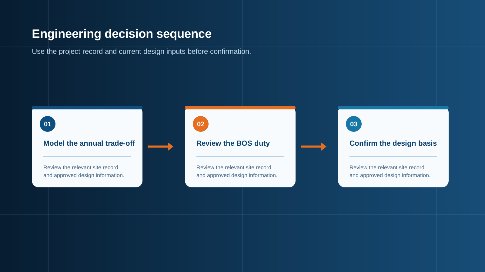
Technical diagram shown at a readable responsive scale.
Worked example
Take a 100 kW inverter fed by a 140 kWp array, giving a ratio of 1.40. Assume the site delivers 1,500 equivalent full-load hours per year for a 1.0 ratio design. Modelling the hourly profile shows that roughly 240 hours per year would have produced more than 100 kW, with an average excess of about 11 kW during those hours. That gives about 2,640 kWh of clipped energy.
The same array without oversizing would have needed a 140 kW inverter and the associated larger alternating-current switchgear. Against a total annual yield in the region of 190,000 kWh, the 2,640 kWh represents about 1.4% — a modest sacrifice for a materially cheaper conversion and connection stage, and for a flatter, more predictable export profile.
When oversizing pays off
Oversizing is most attractive when module pricing per watt is low relative to the cost of conversion and connection equipment, when the grid connection or export licence caps the alternating-current capacity, or when the tariff rewards steady output through the shoulder hours rather than a sharp midday peak.
It also improves winter and cloudy-day performance. On those days the array never approaches its nameplate value, so the additional modules generate at full value with no clipping at all. Many commercial rooftops gain more from that seasonal lift than they lose across a handful of clear summer middays.
When clipping hurts
The economics reverse in several situations. Sites with very high albedo or bifacial rear gain reach the ceiling earlier and for longer than a front-side model predicts. Cool, high-irradiance locations such as mountain plateaus keep cell temperature low, so the array delivers closer to nameplate and the plateau widens.
Contractual exposure also matters. Where a power purchase agreement pays a premium for peak-hour delivery, capping that exact window is expensive. And where the array feeds battery charging through a shared conversion stage, energy lost at the ceiling is energy that never reaches storage, which changes the whole business case.
BOS considerations at high DC/AC ratios
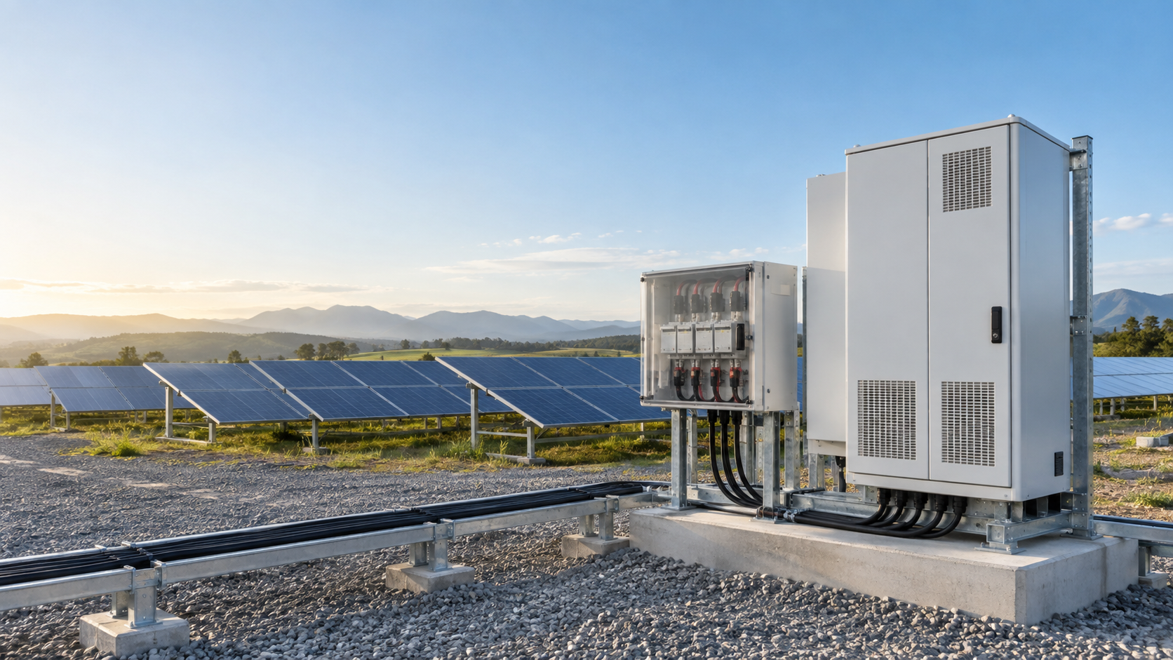
This is where clipping becomes an equipment question rather than a modelling exercise. Everything upstream of the conversion stage must carry the full array current, not the clipped output. A 1.4 ratio design means 40% more direct current flowing through the combiner box, its fuses, its isolator and its busbar than the alternating-current rating suggests.
Ironically, a clipped plant runs its direct-current infrastructure at or near full load for more hours per day than an unclipped one. Continuous-duty thermal margin in the combiner box and busbar therefore deserves more attention, not less.
- String fuses must be rated on string short-circuit current with the usual 1.25 factor, independent of any clipping at the conversion stage.
- Combiner box input count and busbar continuous current rating must cover the full oversized string population.
- The direct-current isolator and its breaking capacity are sized to the array, since it remains live whether or not the output is capped.
- Surge protection on the direct-current side is selected for the maximum system voltage of the enlarged array.
- Cable cross-section and enclosure thermal design must accept the sustained plateau current, which is a longer full-current duty than an unclipped design experiences.
Balancing yield and cost
A sound approach is to model two or three candidate ratios with real hourly irradiance and temperature data for the site, price the complete conversion and connection stage for each, and compare cost per delivered kilowatt-hour rather than headline capacity. In most moderate climates the optimum lands between 1.20 and 1.45, with the clipping penalty comfortably inside a few percent.
Then size the array-side equipment for the array you actually build. Clipping is a deliberate, quantified trade at the conversion stage; it is never a reason to under-specify the protection and collection equipment that carries the direct current to it. NEUTRON reviews string configuration, peak current and enclosure duty against the chosen ratio before releasing a combiner box configuration.
This is general technical guidance. Confirm final ratings, protection coordination, installation and applicable local requirements against current standards, manufacturer documentation and the approved project design.
Frequently asked questions
How much energy is lost to clipping?
For most well-designed arrays the annual loss is small. A DC/AC ratio up to about 1.3 typically loses less than 1% of yearly generation, and a 1.4 ratio commonly costs 1% to 3%. Losses only become significant above roughly 1.6, where they can reach high single digits or more.
Is clipping always bad?
No. Clipping is the price paid for a higher specific yield per kilowatt of conversion capacity, and that trade is usually favourable. The extra modules generate at full value every morning, evening, cloudy day and winter month, which often outweighs a few capped midday hours.
Discuss your PV requirement
Share the system voltage, string arrangement, inverter interface and installation environment. NEUTRON can review the equipment configuration around your project documentation.
Discuss a projectContinue learning
Explore related technical guidance in Solar PV.

Published from the approved Period 06 source package. Technical values and final design decisions must be verified against the current applicable standard, manufacturer documentation and approved project design.