

What oversizing means
The direct-current to alternating-current ratio is installed module capacity divided by the inverter's rated alternating-current output. An array of 13 kilowatts of modules on a 10-kilowatt inverter is a ratio of 1.3. Ratios above 1.0 mean the array can, at peak, produce more than the inverter can deliver — and for a few hours a year it will, at which point the inverter holds its output at its limit and the surplus is simply not harvested.
Oversizing is worthwhile because the array rarely reaches its rating. Module output falls with cell temperature, which on a sunny roof is far above the 25-degree reference used for the nameplate figure, and irradiance reaches the 1000 watts per square metre test level only around solar noon on clear days. Practical peak output is often only seventy-five to eighty-five percent of nameplate, so a ratio of 1.2 to 1.3 barely reaches the inverter limit at all while adding useful production across every low-irradiance hour.
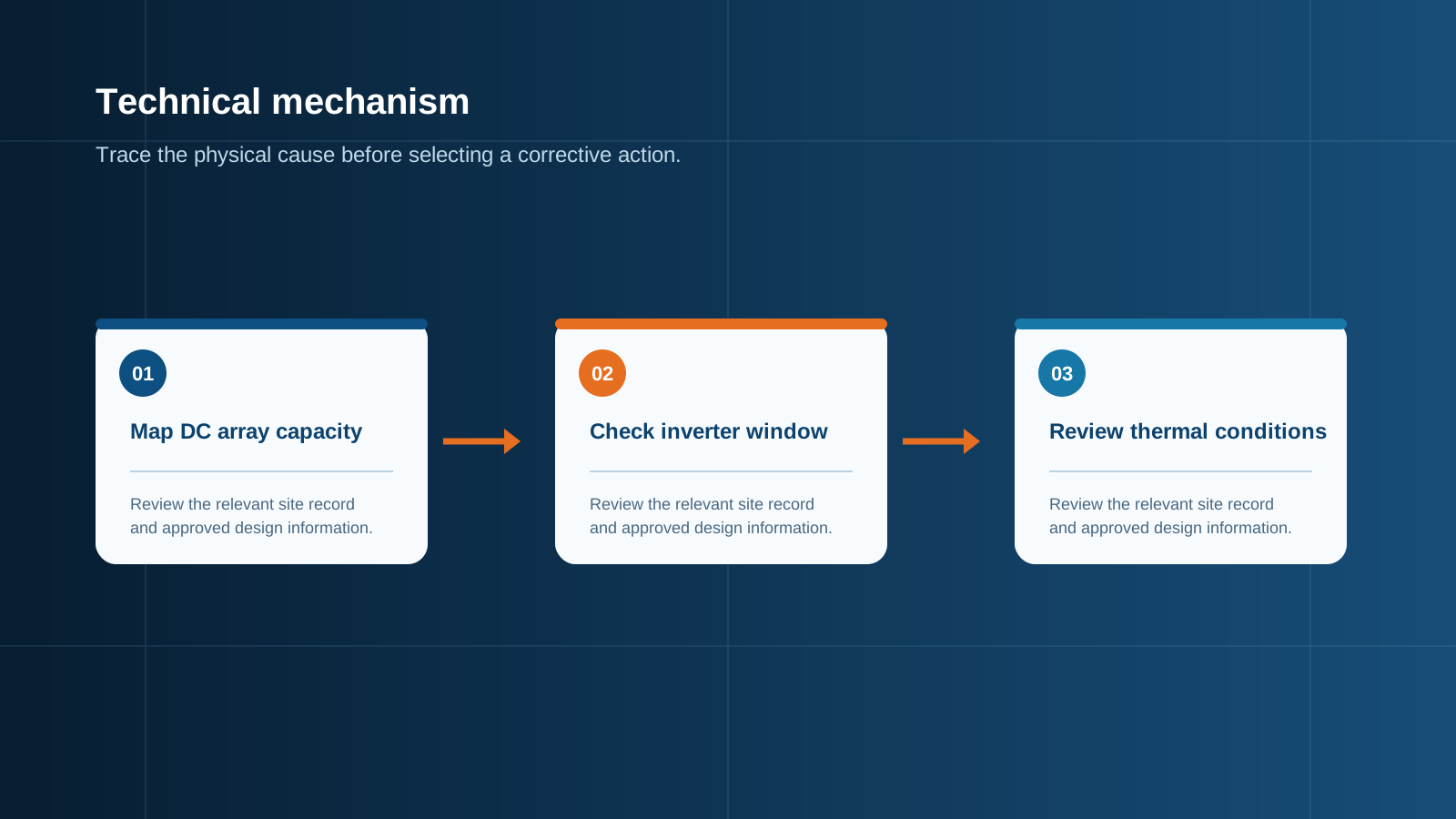
Technical diagram shown at a readable responsive scale.
Safe DC/AC ratios
Most manufacturers permit ratios between 1.2 and 1.5, and many hybrid and commercial units accept up to 2.0 where the array is spread across orientations. The right figure depends on climate, orientation and whether storage is present, but the manufacturer's stated maximum ratio, maximum input current per tracking input and maximum total input current are hard limits, not guidance.
A ratio only records installed capacity. Two systems at the same ratio behave very differently if one faces due south on a steep pitch and the other splits east and west, because the flatter generation curve of the split array clips far less.
- 1.0 to 1.15: conservative, minimal clipping, leaves conversion capacity underused for most of the year.
- 1.2 to 1.35: the common optimum for a single well-oriented plane in a temperate climate.
- 1.35 to 1.5: suited to high-latitude, frequently cloudy or heavily east-west split arrays where peaks are naturally flattened.
- 1.5 to 2.0: appropriate where storage absorbs the surplus, or on multi-orientation arrays with no single sharp peak, and only where the inverter explicitly permits it.
Clipping loss versus yield gain
Clipping is the energy lost when array output exceeds the inverter limit and the operating point is deliberately held back. It is a controlled and non-destructive behaviour, but the lost energy is unrecoverable. The key point is that clipping loss grows non-linearly with the ratio while yield gain grows steadily, so there is an economic optimum rather than a maximum.
As a rough guide for a well-oriented array in a temperate climate, a ratio of 1.2 loses well under one percent of potential annual energy, 1.3 loses roughly one to two percent, 1.4 loses around three to five percent, and 1.5 can exceed five to eight percent. Against that, each step up in ratio adds proportionally more annual production. Because module capacity costs far less per watt than inverter capacity, ratios up to about 1.3 usually improve returns even after clipping is accounted for.
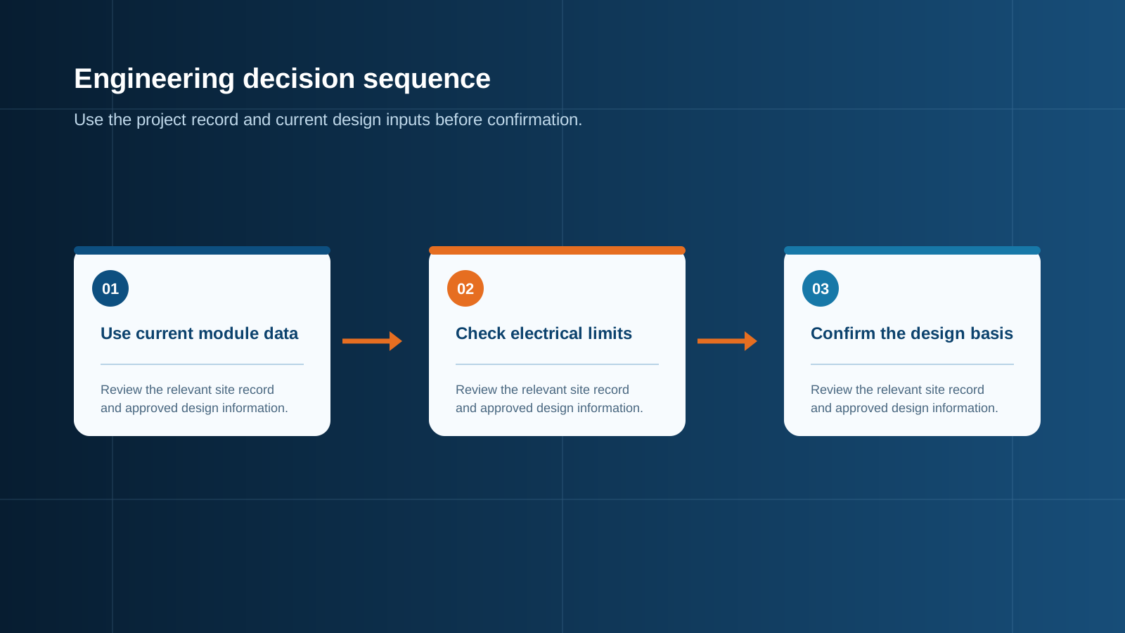
Technical diagram shown at a readable responsive scale.
The voltage trap at low temperature
This is the failure mode that catches designers who focus only on clipping. Clipping is a current and power limit and the inverter handles it gracefully. Voltage is different: exceeding the maximum input voltage is a fault condition that can shut the inverter down or damage it, and it has nothing to do with the ratio.
Module open-circuit voltage rises as temperature falls, typically at around -0.25 to -0.30 percent per degree Celsius below the 25-degree reference. The worst case is a cold, clear morning with the array energised but unloaded, when string voltage is at its absolute maximum. Take a module with a 50-volt open-circuit rating and a coefficient of -0.27 percent per degree at a site reaching -20 degrees: the 45-degree difference gives roughly 12 percent more voltage, so each module presents about 56 volts. A string of 18 modules that reads 900 volts on the datasheet will present around 1008 volts — over a 1000-volt system limit.
Oversizing pressures this directly, because the temptation when adding modules is to lengthen strings. Series count must be fixed by the cold-temperature voltage calculation first; extra capacity is then added as additional parallel strings, never by extending a string that is already at its voltage limit.
A worked calculation
Consider a 10-kilowatt inverter with a maximum input voltage of 1000 volts, two tracking inputs rated 26 amperes each, and a permitted ratio of 1.5. Using 550-watt modules with an open-circuit voltage of 49.5 volts, a maximum-power current of 13.4 amperes, a short-circuit current of 14.2 amperes and a voltage coefficient of -0.27 percent per degree, at a site with a minimum temperature of -10 degrees.
The 35-degree difference from reference raises open-circuit voltage by about 9.5 percent, to 54.2 volts per module. Dividing the 1000-volt limit by 54.2 gives 18.4, so 18 modules per string is the maximum. Two strings of 18 modules give 36 modules, or 19.8 kilowatts — a ratio of 1.98, above the permitted 1.5. Reducing to 27 modules, arranged as one string of 14 and one string of 13 on separate inputs, gives 14.85 kilowatts and a ratio of 1.49, just inside the limit.
Current then needs checking: each string draws 13.4 amperes operating and 14.2 amperes short-circuit, both well inside the 26-ampere per-input rating. Voltage, ratio and current all pass, and the array-side protection is sized on 14.2 amperes per string — which at 1.25 times gives 17.75 amperes, so a 20-ampere photovoltaic fuse per string.
BOS margin at high ratios
The critical principle is that inverter clipping provides no relief whatsoever to the array-side equipment. When the inverter limits its output, the array is still generating: string currents still flow at their full value, conductors still carry them, string fuses still see them and the combining busbar still aggregates them. Everything upstream of the inverter must be rated for the full array output.
A high ratio also means more parallel strings, which means more fused inputs, more terminals and a higher aggregated busbar current. Specifying the combining assembly against the inverter's alternating-current rating rather than the array's direct-current output is the systematic error behind under-rated equipment on oversized plants.
- String overcurrent protection sized on full short-circuit current, corrected for bifacial rear gain, and within the module maximum series fuse rating.
- String and output conductors sized for the full array current with acceptable voltage drop and temperature rise.
- Combining busbar rated for the summed short-circuit current of every parallel string, derated for enclosure internal temperature.
- Isolation devices and surge protection rated for the cold-corrected maximum system voltage, not the nominal figure.
Protection and isolation
Every parallel string requires its own overcurrent device so that a faulted string cannot be back-fed by its healthy neighbours — a risk that grows with the number of parallel strings that oversizing brings. Each tracking input group needs a load-break isolation point rated for direct-current duty at the full system voltage, so one group can be isolated for maintenance while the remainder stays live.
Direct-current surge protection should be located close to the combining point, with a continuous operating voltage and protection level matched to the cold-corrected maximum system voltage. Larger arrays present a larger conductor loop area and collect more induced surge energy, so surge protection selection deserves the same attention as overcurrent protection. Per-string current measurement is also more valuable on oversized plants, since with many parallel strings a single failed string is easily hidden inside a clipped output that looks entirely normal at the meter.
When not to oversize
Oversizing is the wrong choice in several situations. Where the array is a single steeply pitched plane facing the equator in a high-irradiance climate, generation peaks sharply and clipping losses climb quickly, so ratios much above 1.2 waste module capacity. Where an export limit or grid connection agreement already caps output, additional modules may deliver nothing beyond the cap. Where the inverter datasheet states a lower maximum ratio or input current, that figure ends the discussion regardless of the economics.
And where the cold-temperature voltage calculation already places string length at its ceiling, additional capacity must be added as parallel strings with the corresponding protection and busbar capacity — not by lengthening existing strings. NEUTRON reviews the array configuration, ratio and site temperature extremes and prepares a configuration discussion for combining and protection equipment rated for the full oversized array output rather than the inverter rating.
This is general technical guidance. Confirm final ratings, protection coordination, installation and applicable local requirements against current standards, manufacturer documentation and the approved project design.
Frequently asked questions
What DC/AC ratio is safe?
Most inverters permit between 1.2 and 1.5, and many hybrid and commercial units allow up to 2.0 where the array is spread across orientations or paired with storage. For a single well-oriented plane in a temperate climate, 1.2 to 1.35 is the usual economic optimum.
How does cold weather affect it?
Cold raises module open-circuit voltage, typically by around 0.25 to 0.30 percent for every degree below the 25-degree reference. The worst case is a cold, clear morning with the array energised but unloaded, when string voltage peaks.
Discuss your PV requirement
Share the system voltage, string arrangement, inverter interface and installation environment. NEUTRON can review the equipment configuration around your project documentation.
Discuss a projectContinue learning
Explore related technical guidance in Solar PV.


Published from the approved Period 06 source package. Technical values and final design decisions must be verified against the current applicable standard, manufacturer documentation and approved project design.