
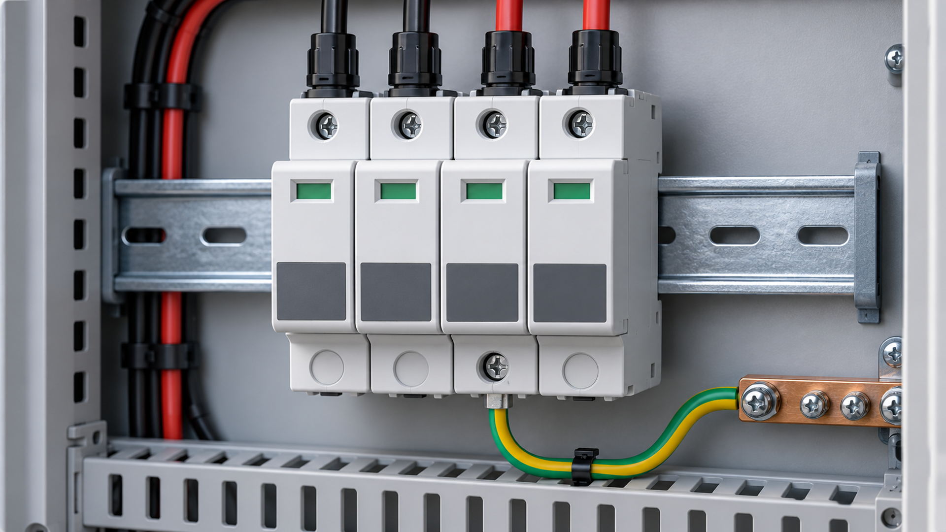
Standard version and scope
IEC 61643-31:2018, the edition discussed here, specifies requirements and test methods for SPDs intended for the DC side of photovoltaic installations. It addresses the performance of the protective device under defined test conditions. A product test record does not establish that a particular installation has the right SPD location, wiring or coordination. Procurement therefore needs both device evidence and a project selection schedule.
Ucpv Is a Device Rating, Not the Array Voltage
Uc is commonly used for maximum continuous operating voltage. For a PV SPD, Ucpv identifies the maximum DC voltage that may be continuously applied to its specified terminals under the stated conditions. It is a rating of the SPD, not the measured array voltage at its mounting point. Calculate the maximum system open-circuit voltage using the applicable temperature and array corrections, then select a suitable SPD Ucpv according to the installation rules and manufacturer instructions. Check the relevant protection modes and grounding arrangement.
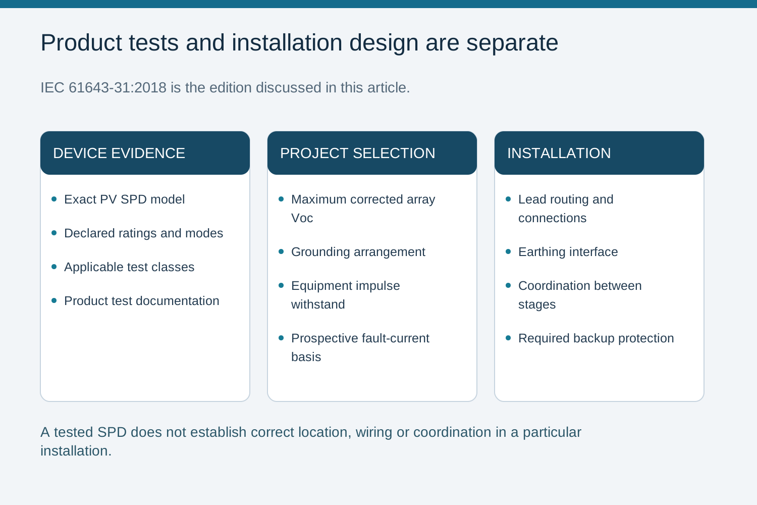
Product test versus system selection
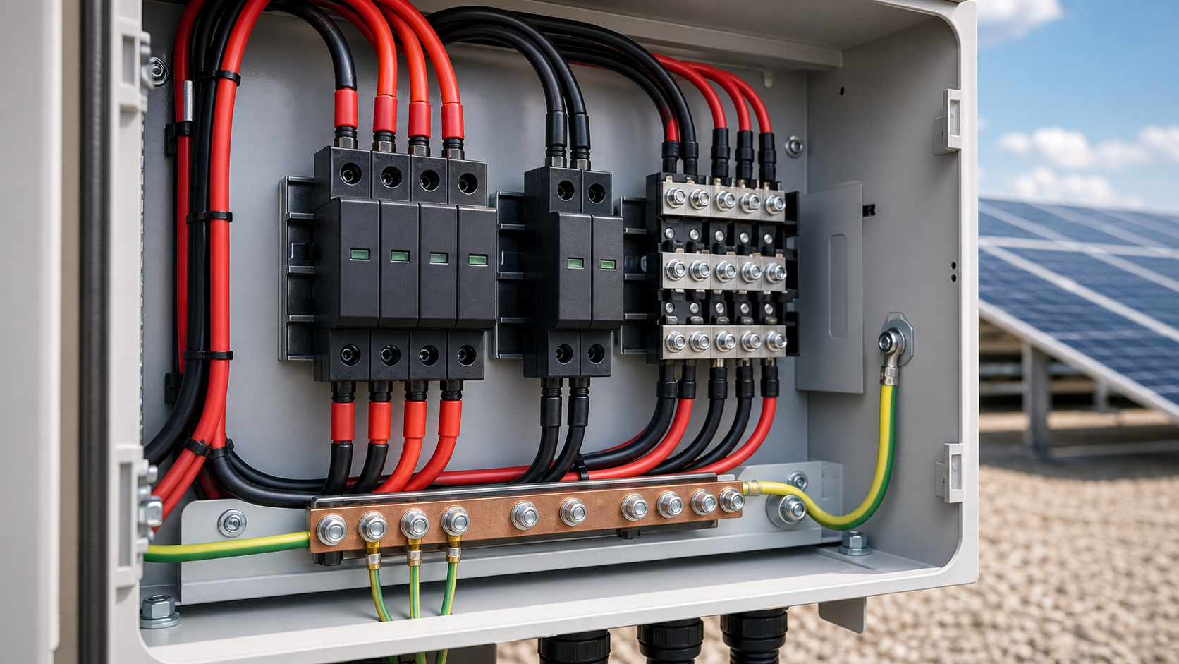
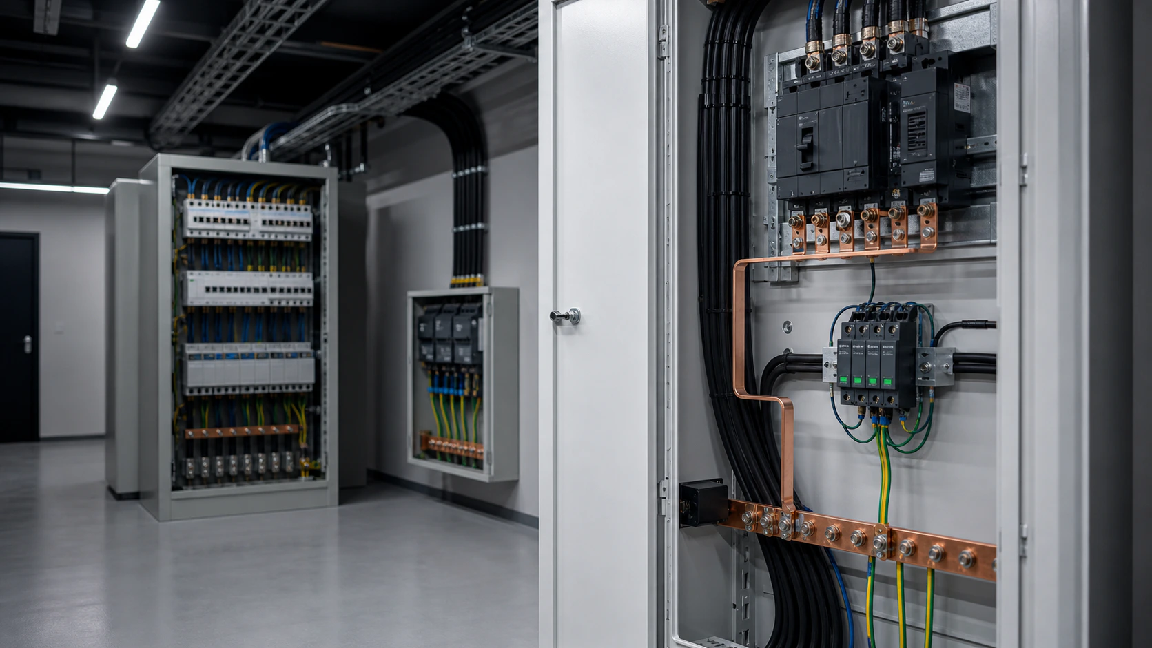
The IEC 61643-31 test record should identify the actual model and declared ratings. Type 1+2 indicates the applicable combination of impulse-test classes, not a mandatory spark-gap and varistor construction. Installation design still determines the protected circuits, lead routing, grounding connections and coordination with other SPDs or backup protection. Devices at different locations are coordinated stages; they are not placed electrically in series with the PV load merely because they form a cascade.
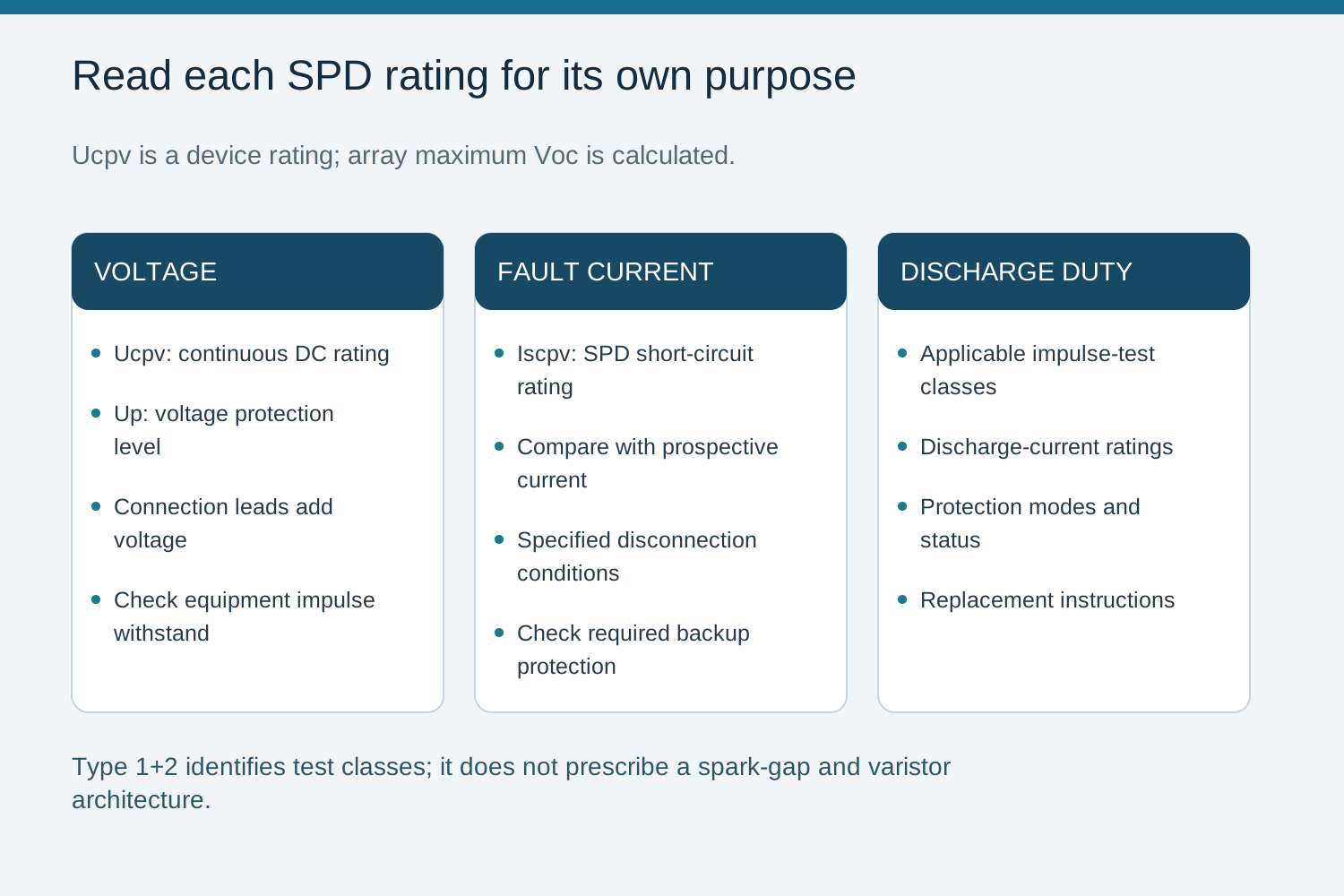
Read the Other Ratings Alongside Ucpv
Check voltage protection level Up against the equipment impulse withstand, including the additional voltage caused by connection leads. Check the SPD short-circuit-current rating Iscpv against the prospective PV fault current and the specified disconnection or backup-protection conditions. Iscpv is not a promise that the device remains reusable after a fault. The selection schedule should also identify discharge-current ratings, protection modes, status indication and replacement instructions.
Include an SPD Schedule in the NEUTRON Enquiry
For a NEUTRON DC combiner configuration discussion, provide the array maximum corrected Voc, grounding arrangement, required SPD type and protection modes, equipment impulse withstand and prospective fault-current assessment. Include any specified SPD model, backup-protection requirements and remote-status interface. These details allow the requested combiner arrangement to be discussed without assuming that all SPD modules or enclosure configurations are interchangeable.
Confirm the applicable installation rules, current manufacturer instructions and exact assembly configuration with a qualified design engineer.
Frequently asked questions
What does IEC 61643-31 cover?
It specifies requirements and test methods for SPDs on the DC side of photovoltaic installations. Correct placement, wiring and coordination require a separate installation design.
Is Ucpv the actual voltage of the PV array?
No. Ucpv is the maximum continuous DC voltage rating for the specified terminals of a PV SPD. The maximum corrected array voltage is calculated separately and used to select an appropriate rating under the applicable rules.
Does a tested SPD mean the system is protected?
No. Testing establishes device performance under stated conditions. Protection also depends on voltage selection, placement, lead connections, fault-current compatibility and coordination.
Is Type 1+2 an internal architecture?
No. Type 1+2 identifies a combination of impulse-test classes. Confirm the model ratings and installation instructions instead of inferring its internal construction from the label.
Bring the design basis to the configuration review.
Provide the module and inverter data, string topology, site conditions and required verification documents.
Discuss a projectContinue learning
Explore related technical guidance in Electrical Protection.
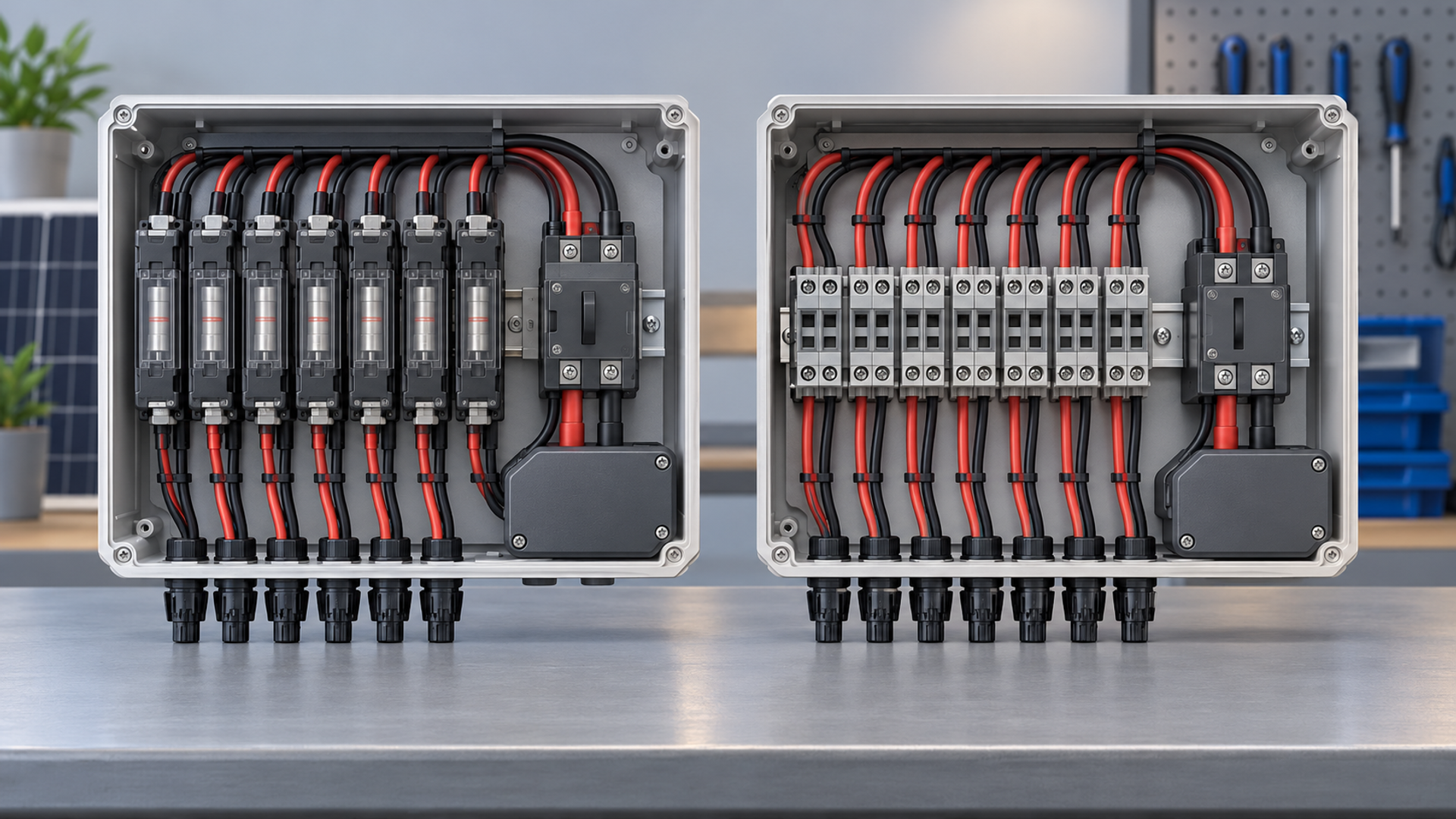
Technical guidance: confirm the exact model, applicable standard edition and project-specific conditions. Illustrations explain engineering decisions and do not certify a product.