
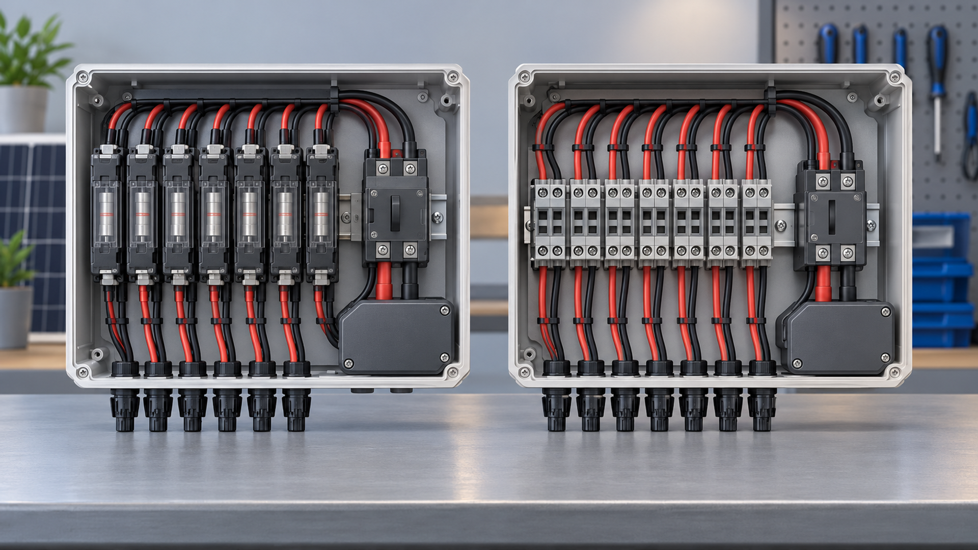
Fused and non-fused: what the labels mean
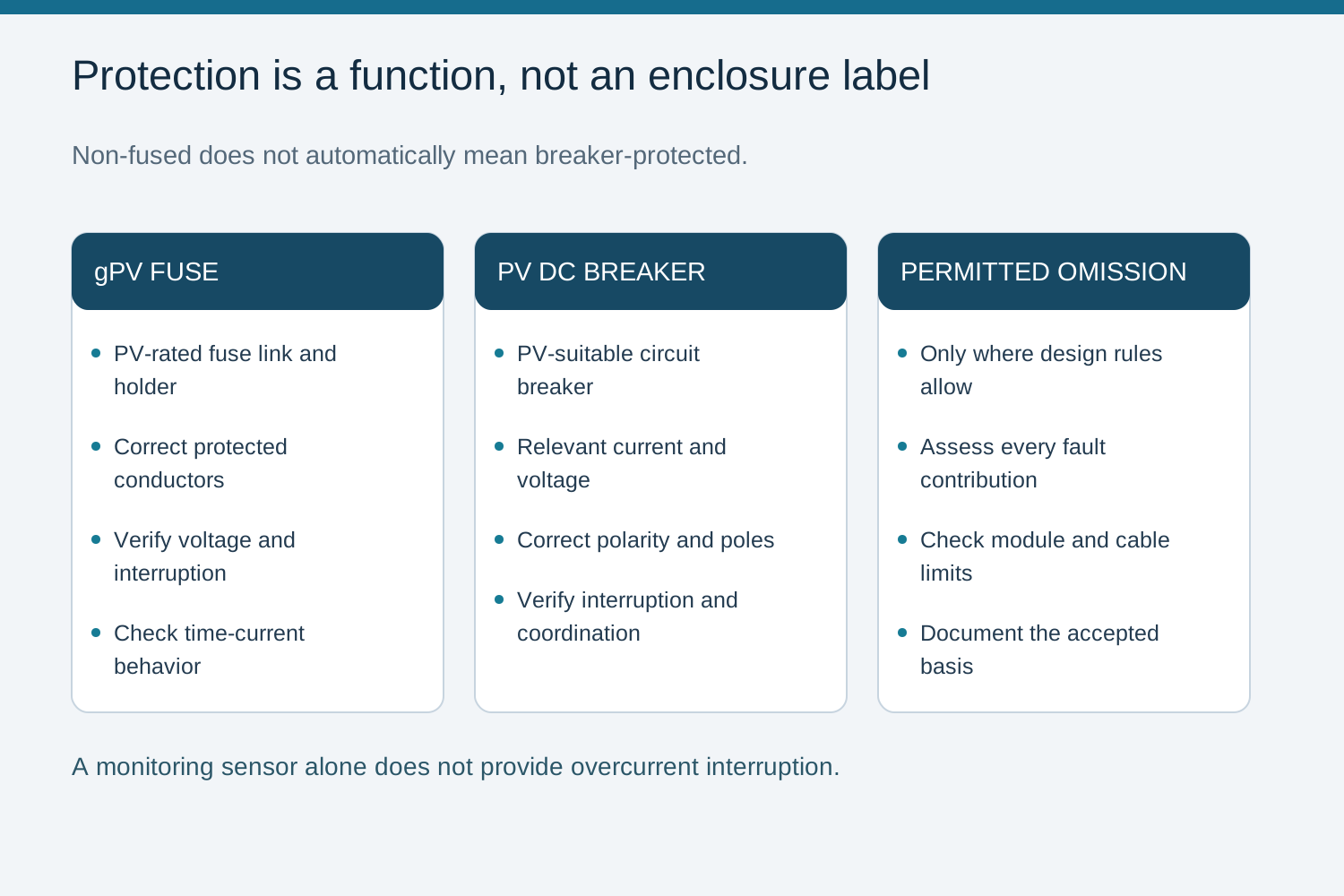
A fused combiner includes string fuse-links. A non-fused combiner omits them, but the label alone does not establish whether a breaker, another approved protective arrangement, or a permitted omission of string overcurrent protection applies. Current monitoring reports a condition; it does not clear overcurrent unless it is part of a protective system with a verified disconnection function. Identify the actual protection on the single-line diagram before selecting the enclosure.
When String Overcurrent Protection Is Needed
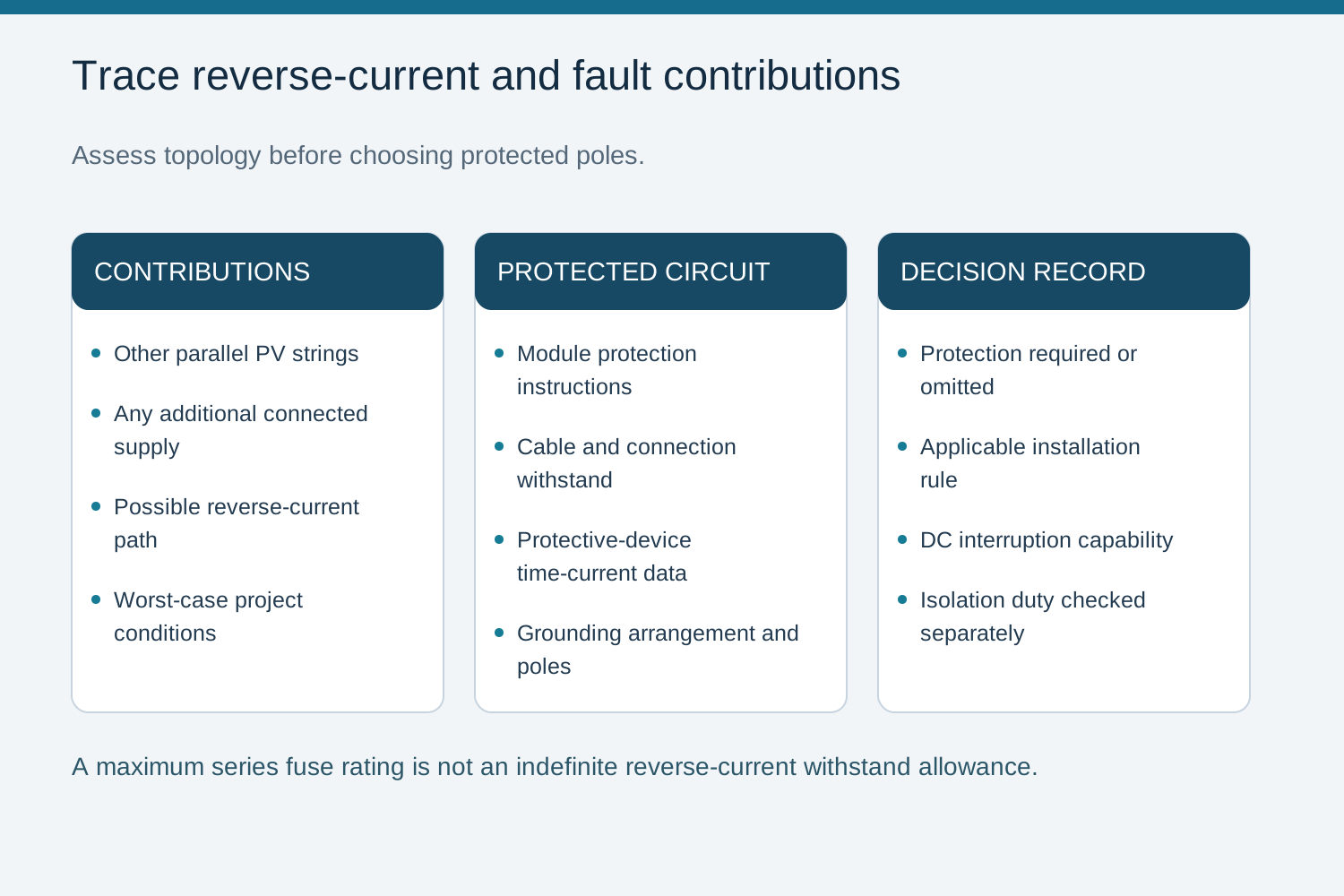
A faulted string may receive reverse current from other parallel strings and any additional connected supply. Evaluate those paths against the module instructions, conductor withstand and applicable installation rules. Where overcurrent protection is required, it may be provided by a suitable gPV fuse or a PV-rated circuit breaker that meets the design requirements. Omission is acceptable only when all applicable protection conditions are satisfied, not merely because one module check passes.
Map every parallel contribution and other possible backfeed path.
Check module, conductor and connection limits alongside the protection functions.
Document the installation rule and equipment instructions used for any omission.
Per-pole fusing is not universal
The conductors requiring protection depend on the grounding arrangement, circuit topology and applicable installation rules. A positive-and-negative fuse pair is not a universal requirement. Equally, a single-pole arrangement is not suitable by default. The project drawing should identify the protected conductors and the required isolation poles separately.
Choose protected poles from the grounding arrangement and applicable rules.
Omit string overcurrent protection only after every required check is satisfied.
Keep isolation requirements separate from overcurrent-protection requirements.
Common mistakes to avoid
Do not equate non-fused with breaker-protected or monitored with protected. A module maximum series fuse rating limits the selected protection rating; it is not a statement that any reverse current below that number can flow indefinitely. Also check the cable limits and the protective device time-current behavior. These distinctions prevent a reduced-parts design from losing necessary fault protection.
Monitoring alone is not an overcurrent-clearing device.
A maximum series fuse rating is not a continuous reverse-current allowance.
A lower component count still requires a complete protection assessment.
Selection steps
Begin with the array topology and worst-case fault contributions. Determine whether each string needs overcurrent protection, then select a suitable device and protected poles. Verify DC voltage, current rating, interruption capability and thermal conditions. Keep the decision and any permitted omission in the design record. A rated switch-disconnector provides switching and isolation; it does not replace the required fuse or circuit breaker.
Send NEUTRON the Protection Decision, Not Just the Label
When discussing a NEUTRON DC combiner or DC breaker configuration, share the module maximum series fuse rating, parallel-string topology, cable details, required protected poles and the engineering decision on whether string overcurrent protection is needed. Include the target installation rules and fault-current assessment. These inputs support a discussion of the required equipment arrangement without assuming that a non-fused or monitored enclosure provides a particular protection function.
Confirm the applicable installation rules, current manufacturer instructions and exact assembly configuration with a qualified design engineer.
Frequently asked questions
Is a non-fused combiner always an MCB design?
No. It means string fuse-links are absent. The design may use suitable breakers, another approved protective arrangement, or a permitted omission of string protection. Monitoring alone does not clear a fault.
When is string overcurrent protection required?
Apply the installation rules and equipment instructions to the available reverse and fault currents, module limits and conductor withstand. If protection is required, an appropriate fuse or PV-rated breaker may provide it. Passing a module check alone does not authorize omission.
Does current monitoring replace a string fuse?
No. Monitoring can identify abnormal current but does not interrupt it on its own. A protective system must include a verified means of disconnection that satisfies the relevant design requirements.
Does a switch-disconnector clear a fault?
A switch-disconnector is for its rated switching and isolation duty. Fault-current clearing must be assigned to suitable protective devices; do not rely on the disconnect as a substitute.
Bring the design basis to the configuration review.
Provide the module and inverter data, string topology, site conditions and required verification documents.
Discuss a projectContinue learning
Explore related technical guidance in Electrical Protection.
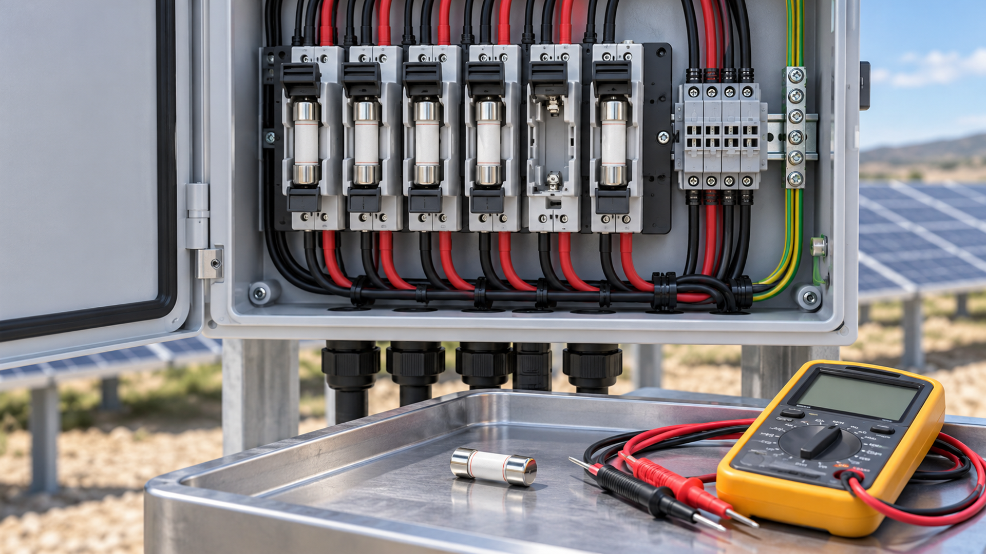

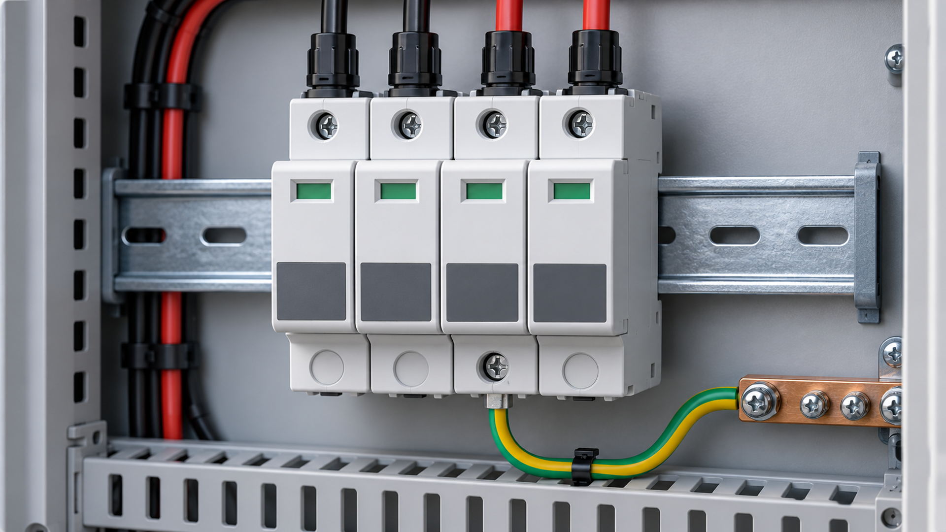
Technical guidance: confirm the exact model, applicable standard edition and project-specific conditions. Illustrations explain engineering decisions and do not certify a product.