
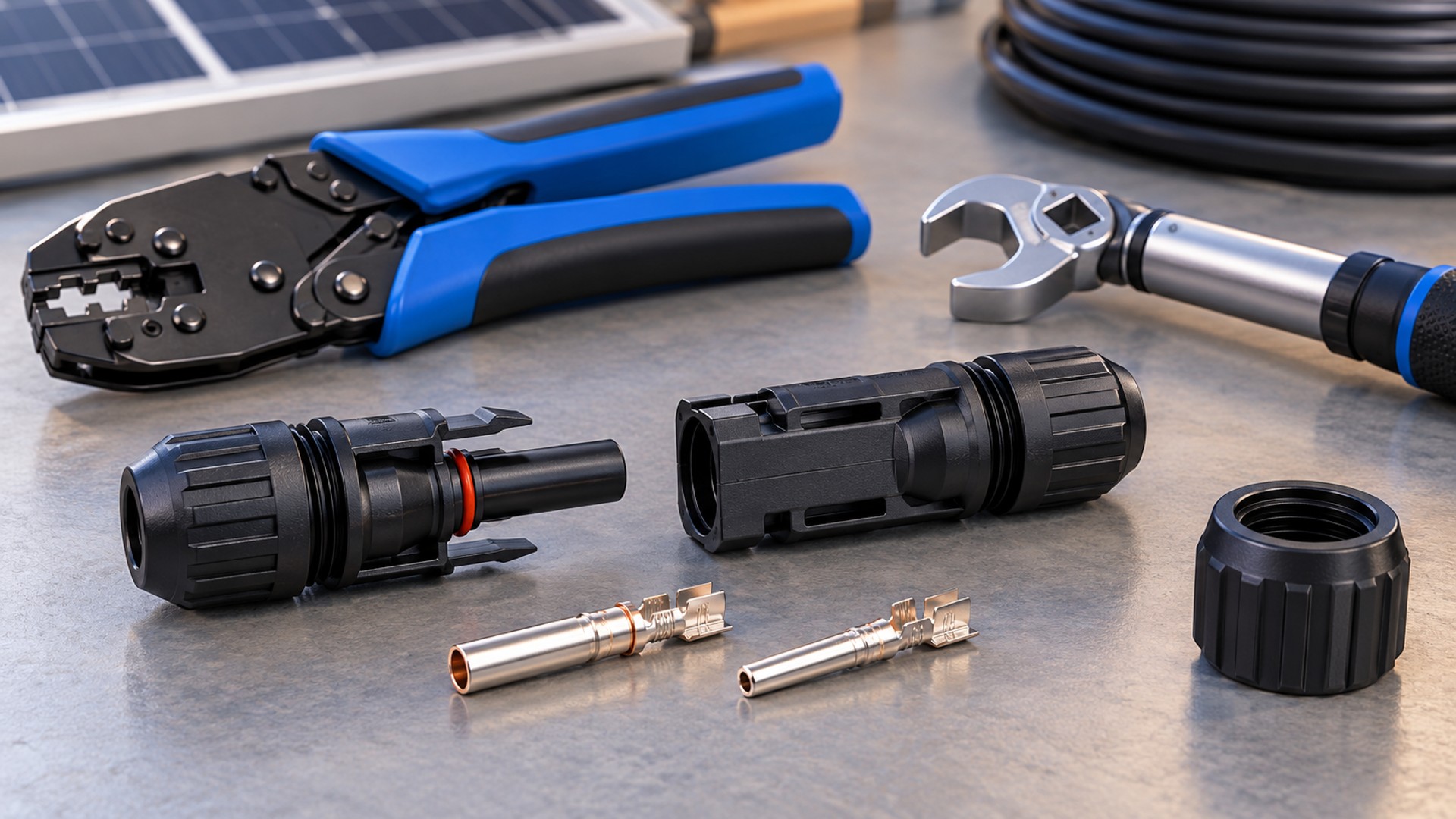
Why a Single Torque Value Is Wrong
Generic figures such as 1.5 to 2.0 Nm for MC4 connectors are misleading because they conflate different torque actions. An MC4 connection involves at least three distinct operations: crimping the contact to the conductor, mating and locking the plug or socket, and tightening the sealing or tail nut that maintains ingress protection. Only the last is a nut torque; the other two are set by dedicated tooling and a click-lock mechanism, not by a torque wrench on the outer housing.
Per-Model Sealing-Nut Torque Reference
The sealing-nut specification comes from the exact connector assembly instruction and the approved cable diameter range. Record the part number and instruction revision before selecting a torque setting. A torque for one connector family is not transferable to another manufacturer's similar-looking housing.
For Stäubli original MC4, consult the applicable MA231 instruction for the connector and cable being assembled. Use the listed tools and follow its sequence. This article deliberately provides no universal sealing-nut setting.
The crimp tool and die control the conductor-to-contact termination. The mating lock is checked through the specified insertion and latch procedure. Neither is adjusted by tightening the cable sealing nut.
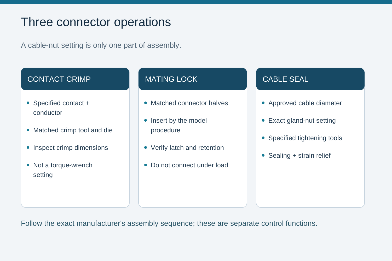
Crimping, Mating Lock and Sealing Torque Distinguished
Crimping establishes the electrical contact resistance and mechanical retention of the pin or socket to the conductor; it must use the specified crimp tool and inspect for correct indentation. Mating lock secures the two halves; a proper lock is confirmed using the model's specified latch and retention checks; fit a separate safety clip only when that model requires it. The tail-nut (sealing nut) torque is what preserves IP rating and strain relief; under- or over-tightening both degrade sealing. Over-tightening can crack the nut or distort the seal; under-tightening lets moisture ingress.
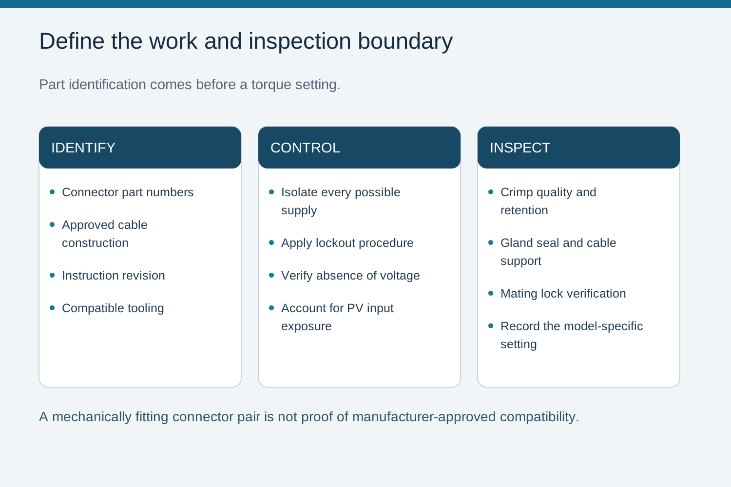
Assembly and Inspection Practice in Combiner Boxes
Before batch assembly, identify the connector part numbers, approved cable, stripping dimensions and specified tooling. Record the required sealing-nut setting and instruction revision, then carry out the manufacturer's inspection and retention checks. Do not mix mating halves merely because they fit mechanically.
Only qualified personnel should perform termination. Isolate all possible supplies, account for illuminated PV conductors and stored energy, and verify absence of voltage at the work location before touching contacts. Never mate or unmate a PV connector under load.
Confirm the applicable installation rules, current manufacturer instructions and exact assembly configuration with a qualified design engineer.
Frequently asked questions
Is 1.5 to 2.0 Nm correct for MC4 sealing nuts?
Do not use a generic setting. Read the current instruction for the exact connector model, cable type and diameter; different families can specify different values.
What torque sets the MC4 electrical contact?
The electrical termination is controlled by the specified crimp tool and die. The cable nut compresses the seal and provides strain relief; it does not set electrical contact pressure.
How is the MC4 mating lock secured?
Follow the connector model's insertion, latch and retention checks. A separate safety clip is required only for models and installations that specify one. Never force a lock by tightening the housing.
What happens if the sealing nut is over-tightened?
It can crack the nut or distort the seal, reducing IP protection. Follow the model-specific torque and verify ingress protection after assembly.
Bring the design basis to the configuration review.
Provide the module and inverter data, string topology, site conditions and required verification documents.
Discuss a projectContinue learning
Explore related technical guidance in Solar PV.
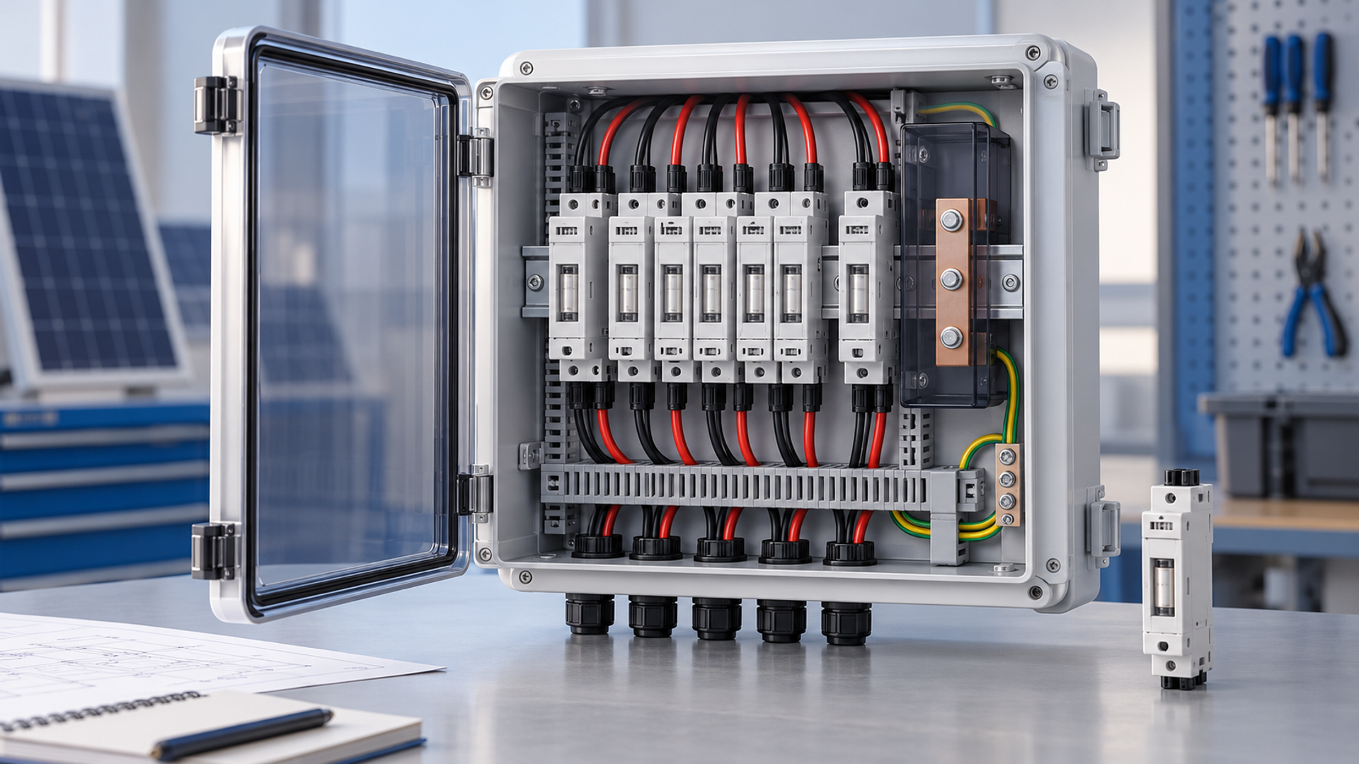


Technical guidance: confirm the exact model, applicable standard edition and project-specific conditions. Illustrations explain engineering decisions and do not certify a product.