
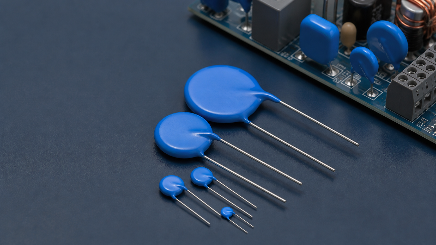
1. What a metal oxide varistor is
Anchor: #what-is-a-metal-oxide-varistor-mov-s1
The name is literal: variable resistor. A MOV is a bulk ceramic component whose resistance depends strongly and symmetrically on the voltage applied across it. Because the response is symmetrical, one device protects both polarities of an AC waveform.
Physically it is a disc of zinc oxide, typically 5 mm to 40 mm in diameter and a few millimetres thick, with metallised electrodes on both faces, radial leads and an epoxy or phenolic coating.
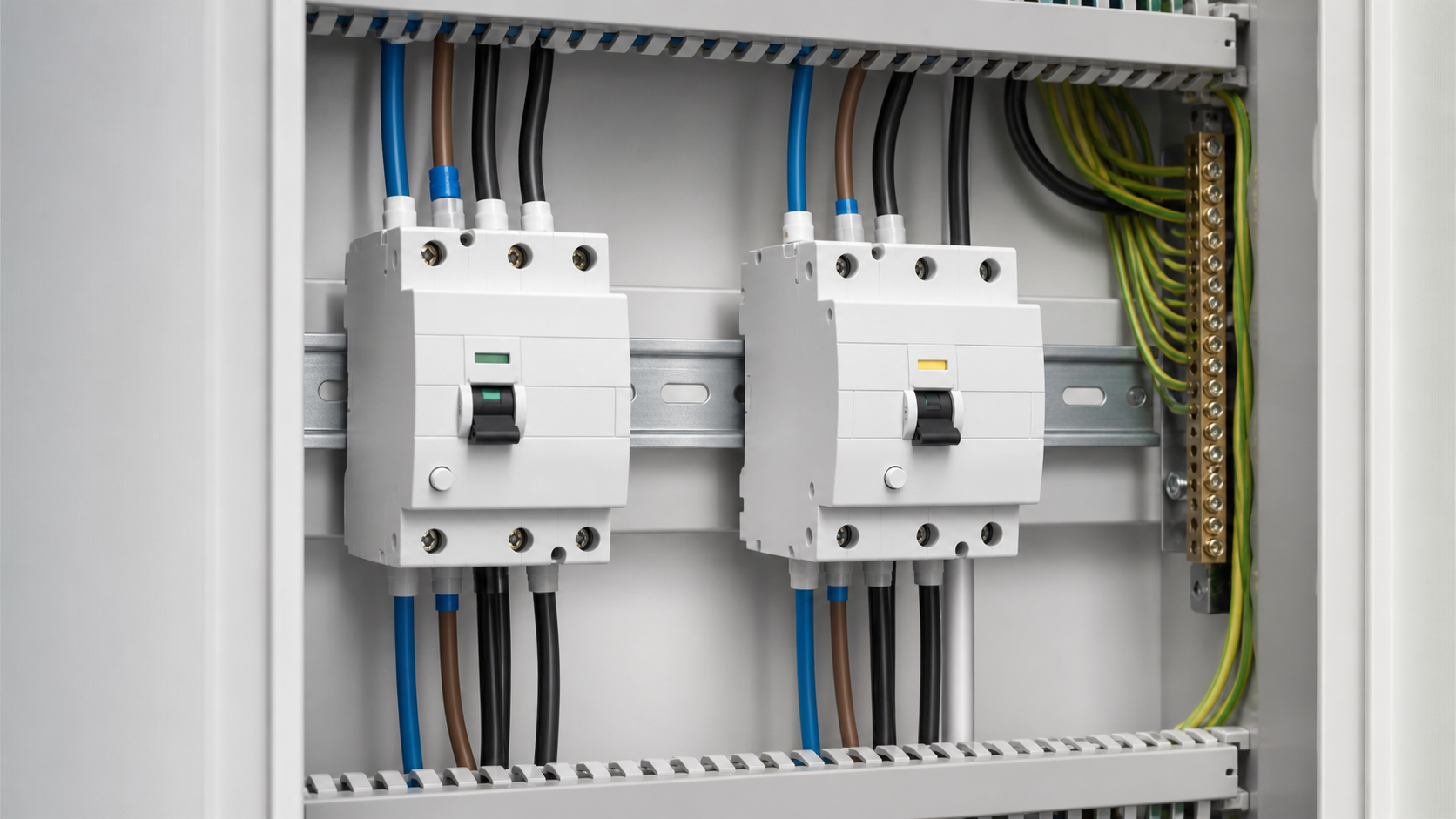
In a surge protective device the disc is not used bare. It sits in a moulded housing with a thermal disconnector, an indicator mechanism and, on plug-in designs, a cartridge that can be exchanged without removing the base from the DIN rail.
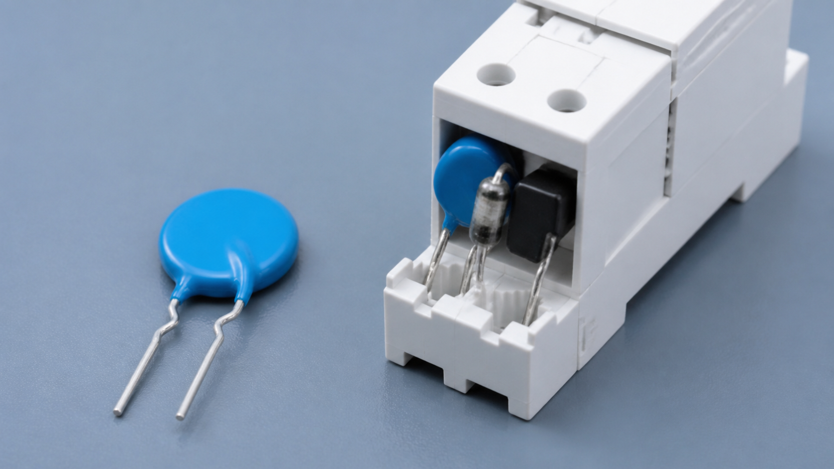
2. Inside the ceramic: the grain boundary effect
Anchor: #what-is-a-metal-oxide-varistor-mov-s2
Zinc oxide alone is a moderately conductive semiconductor. What creates varistor behaviour is the intergranular boundary layer formed when ZnO powder is doped with small quantities of bismuth, antimony, cobalt, manganese and other oxides, then sintered at high temperature.
The result is a dense mass of conductive ZnO grains, each surrounded by a very thin insulating boundary. Each grain-to-grain junction behaves electrically like two Zener diodes connected back to back, with a breakdown of roughly 3.2 to 3.6 V. Current has to cross many such boundaries in series to pass through the disc, so:
This is why thickness and diameter are specified independently: thickness selects the operating voltage, diameter selects the survivable energy. It also explains why a MOV is inherently a bulk device — surge current flows through millions of parallel grain paths simultaneously, which is what allows a small ceramic disc to absorb kiloamperes for tens of microseconds.
- Varistor voltage ≈ 3.2–3.6 V × number of boundaries in series, which is set by disc thickness.
- Energy and current capability are set by the electrode area, which is set by disc diameter.
| Parameter | Symbol | What it means | How to choose it |
|---|---|---|---|
| Maximum continuous operating voltage | Uc | Highest RMS voltage the device tolerates indefinitely | At least 1.1–1.2 × nominal phase voltage; 275 V typical on a 230 V system |
| Varistor voltage | U1mA | Voltage at 1 mA DC — the reference point of the curve | Manufacturer data; must sit above peak line voltage |
| Nominal discharge current | In | 8/20 µs current the device survives repeatedly (usually 15–20 times) | 20 kA for main boards, 5–10 kA for sub-boards |
| Maximum discharge current | Imax | 8/20 µs current survivable once | Typically 2–4 × In |
| Voltage protection level | Up | Let-through voltage at In — the number that protects equipment | Below the equipment's rated impulse withstand voltage |
| Energy rating | W | Absorbable energy in joules for a stated waveform | Compare only within the same waveform |
| Response time | t | Delay from overvoltage to conduction | Intrinsically sub-nanosecond; module response typically <100 ns |
| Temporary overvoltage withstand | UT | Behaviour during a sustained mains fault | Required by IEC 61643-11 for LV SPDs |
3. The V-I curve and what clamping really means
Anchor: #what-is-a-metal-oxide-varistor-mov-s3
The MOV characteristic is described by I = k · Vᵅ, where α is the non-linearity coefficient. For a good zinc-oxide varistor α typically falls between 25 and 50, compared with α ≈ 1 for an ordinary resistor. A high α means the current can rise by six orders of magnitude while the voltage rises by well under a factor of two.
Three regions define the curve:
Clamping voltage is simply the voltage measured across the device at a stated test current, usually the nominal discharge current on an 8/20 µs waveform.
- Leakage region — below the varistor voltage. Current is in the microampere range and behaviour is dominated by the boundary capacitance and temperature.
- Normal varistor region — the steep, highly non-linear section where protection happens. This is where the device operates during a surge.
- Upturn region — at very high current, the bulk resistance of the ZnO grains themselves dominates and the curve flattens back out. Clamping performance degrades here, which is why oversizing matters.
4. Where the surge energy goes
Anchor: #what-is-a-metal-oxide-varistor-mov-s4
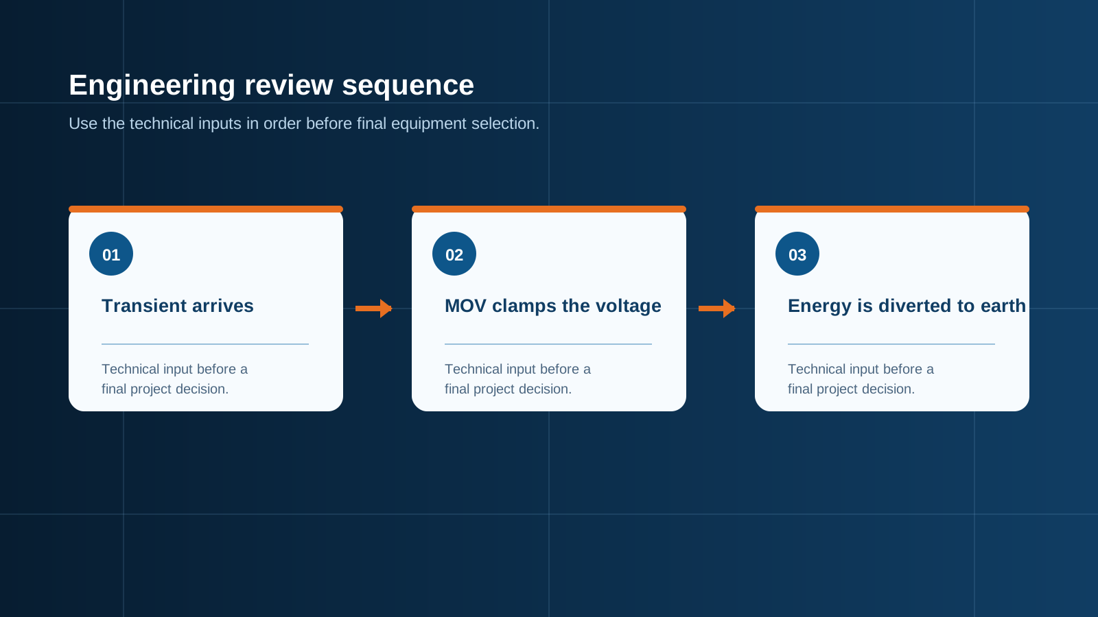
During normal operation at 230 V, a varistor rated for that system is deep in its leakage region and effectively invisible to the circuit. When a transient arrives, the sequence takes nanoseconds:
Step five is the limitation.
- The transient drives the voltage across the MOV above the varistor voltage.
- Grain boundaries break down and the disc conducts, its resistance falling from hundreds of megohms to a fraction of an ohm.
- Surge current diverts through the MOV to neutral or earth instead of through the load.
- The voltage across the protected circuit is held at the clamping level for the duration of the event.
- Surge energy is converted to heat inside the ceramic body.
- As the transient decays, the varistor returns to its high-resistance state and normal operation continues uninterrupted.
5. The parameters that matter when specifying
Anchor: #what-is-a-metal-oxide-varistor-mov-s5
Two rules resolve most selection arguments.
6. Why MOVs age and eventually fail
Anchor: #what-is-a-metal-oxide-varistor-mov-s6
MOV degradation is cumulative and largely irreversible. Each surge causes localised heating at the grain boundaries carrying the most current. Over many events the boundary layers thin, the varistor voltage drifts downward, and leakage current at normal operating voltage rises from microamperes toward milliamperes.
Rising leakage produces continuous internal heating, which accelerates further degradation — a positive feedback loop that ends in thermal runaway. An unprotected varistor in this state can crack, vent or ignite. Three additional stressors accelerate the process:
There is therefore no fixed service life for an SPD module. Life depends on strike exposure, grid quality and installed temperature. Replacement must be driven by condition monitoring, not by a calendar.
- Temporary overvoltage (TOV) — a sustained rise, for example from a lost neutral, applies voltage above Uc for seconds rather than microseconds. This is far more damaging than a lightning transient.
- High ambient temperature — leakage current rises with temperature, so a densely packed enclosure shortens life.
- Undersizing — a device operating in the upturn region of its curve dissipates disproportionate energy.
7. Thermal disconnection and status monitoring
Anchor: #what-is-a-metal-oxide-varistor-mov-s7
Because varistor end-of-life is a fire risk, IEC 61643-11 requires a safe failure mode.
Disconnection must be visible and, ideally, remotely reportable:
A separate backup overcurrent device in series with the SPD, commonly a 32 A fuse on the line conductor, handles the case where the varistor fails to a short circuit faster than the thermal element can respond.
- Local indicator — a window that shows green in normal service and red once the module has disconnected.
- Remote signalling contact — a volt-free changeover or normally-open contact wired to a BMS or SCADA input, so an unmanned substation reports its own loss of protection.
- Plug-in cartridges — allowing a failed module to be exchanged individually without shutting down the board.
8. NEUTRON WCU8 modules and application data
Anchor: #what-is-a-metal-oxide-varistor-mov-s8
NEUTRON's WCU8 series implements the design described above for AC 50/60 Hz distribution systems rated 230 V and 440 V, limiting lightning-induced and switching overvoltages and reducing the overvoltage category endured by downstream equipment by one level.
Ordering uses an explicit code — for example WCU8-D10/4-385-X denotes maximum continuous operating voltage 385 V, 3P+N, fault output signal contacts fitted, maximum discharge current 10 kA.
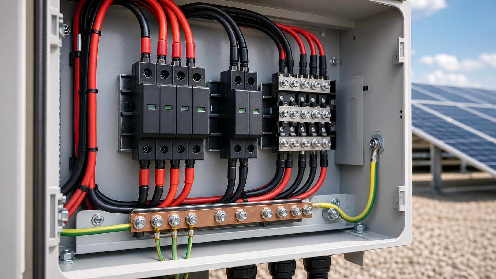
WCU8 modules are fitted as standard in NEUTRON PV combiner boxes, distribution cabinets, grid-connection panels and package substation LV compartments, and are available loose for panel builders.
- Nominal discharge current In (8/20 µs): 20 kA and 40 kA module variants.
- Maximum continuous operating voltage Uc: 275 V and 320 V variants.
- Response time: below 100 ns.
- Construction: DIN rail base plus detachable plug-in cartridges, 18 mm per module, individually replaceable while the installation stays energised.
- Failure disconnection: integral thermal disconnector that isolates a module that overheats or breaks down, with an indicator showing green in service and red after disconnection.
- Remote signalling: normally-open contact rated AC 36 V / 1 A that closes when one or more modules fail; audible and visual alarm units can be added.
- Wiring: copper conductors 2.5–35 mm², earthing conductor 4 mm² minimum, total connecting and earthing conductor length not exceeding 50 cm.
- System configurations: L-N and L-PE modules plus dedicated N-PE modules for TT, TN-S and TN-C systems, including the “3+1” arrangement and Kelvin connection.
Technical diagram shown at a readable responsive scale.
9. Specification checklist and common mistakes
Anchor: #what-is-a-metal-oxide-varistor-mov-s9
Common mistakes: selecting Uc at exactly the nominal voltage, so the varistor ages under normal grid variation; comparing joule ratings across different waveforms; assuming a MOV protects against sustained overvoltage — it does not, and a lost neutral will destroy it; installing modules with long earthing conductors and losing the benefit of a low Up; and never inspecting the status window, so the board runs unprotected after disconnection.
Surge protection reduces risk rather than eliminating it. Selection, installation and periodic inspection must be carried out by qualified personnel under the wiring rules of the destination market.
- Set Uc from the actual maximum operating voltage of the network, not the nominal figure.
- Match In to the installation position — higher at the main board, lower at sub-boards.
- Verify Up against the rated impulse withstand voltage of the protected equipment, allowing for lead-length voltage rise.
- Confirm a thermal disconnector and status indicator are integral to every module.
- Specify the backup fuse or breaker rating in series with the SPD.
- Keep total connecting and earthing conductor length at or below 50 cm and use the V-shaped Kelvin connection.
- Add remote signalling wherever the board is unmanned.
Frequently asked questions
Anchor: #what-is-a-metal-oxide-varistor-mov-faq
Q: What does a metal oxide varistor do?
A: It acts as a voltage-dependent resistor. Below its varistor voltage it is almost non-conducting; above it, its resistance collapses within nanoseconds and it diverts surge current away from the protected circuit, holding the voltage at a defined clamping level and dissipating the surge energy as heat.
Q: What is the difference between clamping voltage and Up?
A: Clamping voltage is measured across the varistor itself at a stated test current. Up, the voltage protection level, is the let-through voltage of the complete surge protective device at its nominal discharge current. Up is the figure to compare against the rated impulse withstand voltage of the protected equipment.
Q: Why do MOVs fail?
A: Every surge causes localised heating at the grain boundaries, so the varistor voltage drifts downward and leakage current rises. Rising leakage causes continuous internal heating, which accelerates degradation and can end in thermal runaway. Sustained temporary overvoltage, such as a lost neutral, is far more damaging than a lightning transient.
Q: How do I know when to replace an SPD module?
A: Check the status indicator. Compliant modules include a thermal disconnector and a window that shows green in normal service and red once the module has disconnected. A remote signalling contact lets the same condition be reported to a BMS or SCADA system in unmanned installations.
Q: Can a MOV protect against sustained overvoltage?
A: No. A varistor is designed for microsecond transients. A sustained overvoltage above Uc, for example from a broken neutral conductor, will overheat and destroy it. Protection against that condition requires overvoltage relays or breakers with over- and undervoltage release functions.
Q: What MOV-based surge protection does NEUTRON manufacture?
A: NEUTRON produces the WCU8 modular surge protective device range for 230 V and 440 V AC systems, with 20 kA and 40 kA nominal discharge current variants, Uc of 275 V or 320 V, response below 100 ns, 18 mm plug-in replaceable cartridges, integral thermal disconnection with green/red status indication and an AC 36 V / 1 A remote signalling contact.
Talk to a NEUTRON engineer
Send your single-line diagram, ratings and destination-market standards. NEUTRON engineering returns a specification-matched proposal with drawings, test scope and lead time.
This is general technical guidance, not a substitute for local electrical code, the applicable standard, product datasheets or a qualified engineer's design review. Confirm ratings and final configurations against the actual project.
Bring the project inputs to the first review.
NEUTRON can review the application context, electrical envelope, enclosure conditions and document requirements related to what is a metal oxide varistor (mov)? how it stops surges before quotation.
Discuss a technical requirementContinue learning
Explore related technical guidance in Electrical Protection.

Converted from the approved Period 01 source article for What is a Metal Oxide Varistor (MOV)? How It Stops Surges. Editorial instructions, duplicate anchor placeholders and embedded publishing directions were removed; the technical body is retained for educational use.