
1. The quick answer
The choice is not really about the devices. It is about how much of the installation you are willing to lose when one appliance develops a fault. With a grouped RCCB the answer is every circuit behind it. With RCBOs the answer is one.
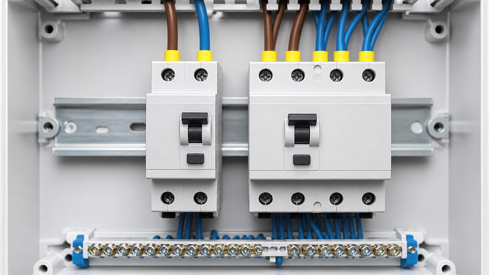
- RCCB (IEC 61008-1) — Residual Current Circuit Breaker. Detects earth leakage. No overcurrent protection. Must be backed by an upstream overcurrent device. Normally protects a group of circuits.
- RCBO (IEC 61009-1) — Residual Current Breaker with Overcurrent protection. Detects earth leakage and provides overload and short-circuit protection. Normally protects one circuit.
2. What an RCCB is — and is not
An RCCB continuously compares the current flowing out on the line conductor with the current returning on the neutral. In a healthy circuit they are equal. If some current escapes to earth — through faulty insulation, a damaged appliance or a person — the difference is detected and the device opens.
What it does not do is protect against overload or short circuit. An RCCB has a rated current such as 40 A, 63 A or 80 A, but that is a thermal carrying capacity, not a protective setting. It will happily pass 100 A through a 63 A device until something upstream clears the fault. This is why an RCCB always requires a correctly rated overcurrent device ahead of it, and why the RCCB rating must be at least equal to that device.
In a conventional board, one RCCB sits between the main switch and a group of MCBs, protecting all of them collectively. That is cheap, compact for small boards, and simple to wire — provided every neutral in the group is returned through the RCCB's own neutral path.
| Characteristic | RCCB | RCBO |
|---|---|---|
| Product standard | IEC 61008-1 | IEC 61009-1 |
| Residual current protection | Yes | Yes |
| Overload protection | No | Yes |
| Short-circuit protection | No | Yes |
| Upstream overcurrent device required | Yes, mandatory | No |
| Circuits protected | A group | One |
| Effect of an earth fault | Whole group de-energised | One circuit de-energised |
| Fault diagnosis | Sequential elimination required | Immediate — the tripped device identifies the circuit |
3. What an RCBO does differently
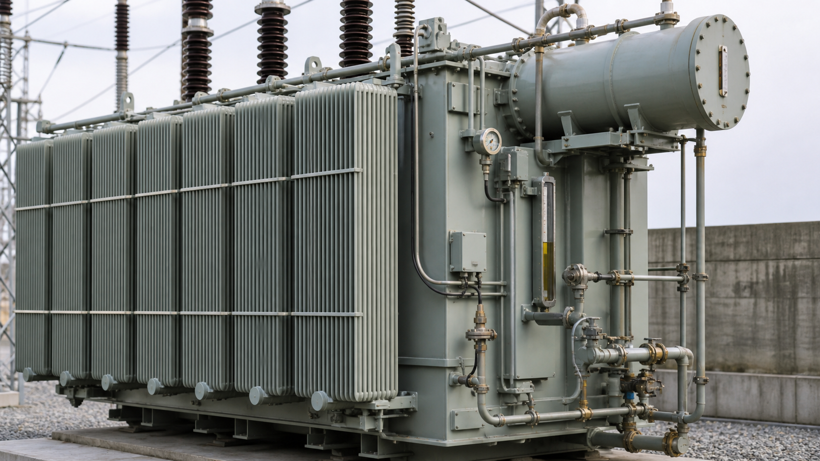
An RCBO packages the residual current sensing element of an RCCB with the thermal-magnetic mechanism of an MCB in a single module. One device, two protection functions, one circuit.
That last point is worth more than it appears. Fault-finding on a grouped RCCB board means isolating circuits one at a time and re-energising until the fault reappears. On an RCBO board the device with the tripped handle *is* the diagnosis.
- Overload protection via the calibrated thermal element, selected by curve — Type B, C or D.
- Short-circuit protection via the magnetic element, with a rated breaking capacity typically 6 kA or 10 kA.
- Residual current protection at the chosen sensitivity, commonly 30 mA for additional protection.
- Individual isolation. A fault on one circuit affects only that circuit.
- Individual diagnosis. The tripped device identifies the faulty circuit immediately — no sequential testing to find which of eight circuits caused the trip.
5. The space argument: module width maths
DIN modules are 17.5–18 mm wide, and enclosure capacity is fixed. The common assumption that RCBOs consume more space deserves an actual calculation.
The conclusion is specification-dependent, which is exactly why the assumption is unreliable. Single-module (compact) RCBOs occupy less width than an RCCB plus MCB group while giving per-circuit protection. Two-module RCBOs occupy more. If panel space is the constraint on a retrofit — and in a full consumer unit or a crowded riser board it usually is — specifying single-module RCBOs can be the only way to add residual current protection to every circuit without replacing the enclosure.
There is a second space consideration that schedules rarely capture: wiring volume. A grouped RCCB arrangement requires a separate neutral bar for each RCCB group plus the general neutral bar, and the neutral conductors from every circuit in the group must be routed to the correct bar. RCBOs land each circuit neutral on its own device. In a tight enclosure the reduced conductor congestion matters for both heat and workmanship.
6. Accumulated leakage and nuisance tripping
This is the strongest technical argument for RCBOs and the one most often missed at design stage.
Every item of electronic equipment leaks a small standing current to earth through its EMC filtering — typically a fraction of a milliamp to a few milliamps per device. Those leakages are cumulative across all circuits behind a single RCCB. A 30 mA RCCB is required to trip between 15 mA and 30 mA, so it may operate at as little as half its rated sensitivity.
Put twenty devices with 0.5 mA of standing leakage each behind one 30 mA RCCB and the baseline is already 10 mA. Add a damp morning, a slightly degraded heating element and a motor start, and the device trips — with no actual fault present. The installation then loses every circuit in the group, often including lighting, and someone has to find a torch.
- RCBOs distribute the leakage budget. Each device sees only its own circuit's standing leakage, so the margin to the trip threshold stays wide.
- Nuisance trips become circuit-specific, which converts a mysterious intermittent fault into an obvious one.
- Critical circuits stay energised. Refrigeration, alarms, IT equipment and emergency lighting are not collateral damage.
- Where an RCCB is retained, split the load across at least two devices and never place all lighting behind the same device as all socket circuits.
7. Discrimination and selectivity
Where residual current devices are installed in series — a main device at the origin and final-circuit devices downstream — they must discriminate, so the device closest to the fault operates first.
In practice this means a board with a 300 mA S-type main device for fire protection and 30 mA RCBOs on final circuits gives both selectivity and per-circuit isolation — a combination that a single grouped RCCB cannot deliver.
- Current discrimination. The upstream device should have a rated residual current at least three times that of the downstream device — typically 100 mA or 300 mA upstream against 30 mA downstream.
- Time discrimination. The upstream device should be a selective S-type, which introduces a deliberate delay before tripping and allows the downstream device to clear first.
- Both are needed. Current discrimination alone is unreliable, because a general-type upstream device can trip faster than the downstream one on a high residual current.
- Do not use an S-type device for additional personal protection at 30 mA — the delay defeats the purpose.
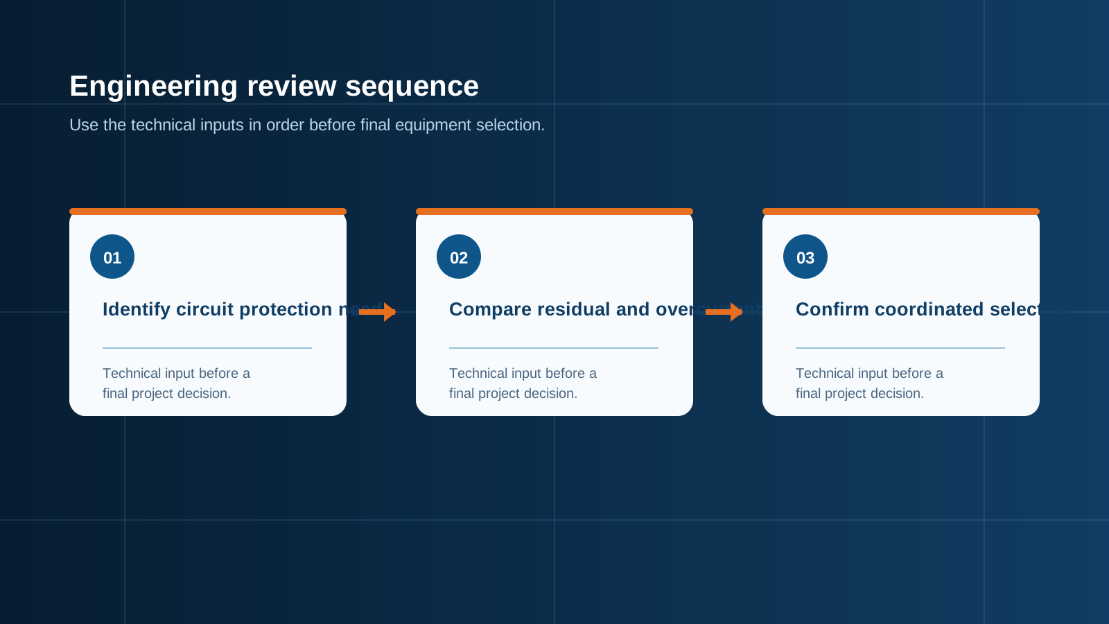
Technical diagram shown at a readable responsive scale.
8. Choosing the right residual current type
Selecting the type is not optional refinement. A Type AC device can be blinded by a DC residual component — a smooth DC leakage current can saturate the detection core so the device fails to trip on a subsequent AC fault. Any circuit feeding EV charging equipment, a PV inverter or a variable-speed drive needs the correct type, and this applies equally to RCCBs and RCBOs. Where the load is unknown, Type A is the sensible baseline for general circuits.
9. Lifetime cost, not sticker price
Compare like for like. The honest comparison is not one RCBO against one RCCB — it is one RCBO against one RCCB plus one MCB plus a share of the group's downtime.
The break-even is straightforward: if a single grouped nuisance trip per year costs more than the RCBO premium for the whole board, RCBOs are the cheaper option from day one.
- Device cost. An RCBO typically costs more than an MCB plus a proportional share of an RCCB, but the gap has narrowed considerably as volumes have grown.
- Installation labour. RCBOs simplify neutral routing and remove the need for multiple RCCB neutral bars.
- Fault-finding labour. Every grouped-RCCB nuisance trip that requires an electrician to attend and eliminate circuits sequentially costs more than the price difference of several RCBOs.
- Downtime. In commercial and light industrial premises the cost of losing a group of circuits during trading hours dwarfs the hardware difference.
- Consequential loss. Refrigeration, servers, process equipment and security systems behind a grouped device are exposed to a fault on any other circuit in the group.
10. When an RCCB is still the right answer
A hybrid arrangement is often the best engineering answer: an S-type RCCB at the origin for fire protection, RCBOs on circuits where continuity matters, and a grouped RCCB with MCBs on circuits where it does not.
- Small boards with few circuits where grouping loses little.
- Budget-constrained projects where per-circuit protection cannot be justified and downtime carries no commercial cost.
- Upstream fire protection, where a 300 mA S-type device at the origin is the correct application and per-circuit protection sits downstream.
- Non-critical outbuildings and temporary installations.
- Where the enclosure genuinely cannot accept the RCBO width and single-module devices are unavailable in the required rating or type.
11. NEUTRON panel build practice
NEUTRON builds distribution boards and switchgear with the residual current strategy configured per project, wired and routine-tested before shipment.
Boards are supplied with a labelled circuit schedule, the wiring diagram inside the door, and a routine test record including residual current device trip time verification at rated and five times rated residual current.
Safety and limitations: residual current device selection, sensitivity and type are governed by the national wiring regulations of the installation country, and requirements differ significantly between markets. Residual current protection reduces but does not eliminate the risk of electric shock, and does not protect against line-to-neutral contact. All work must be carried out by qualified electrical personnel, and test buttons should be operated at the interval stated by the applicable regulations.
Next step
Planning a board build or panel upgrade? Send your circuit schedule, load types, earthing arrangement and enclosure constraints. NEUTRON engineering will return a residual current strategy and a wired, tested board specification.
Browse distribution boards and protection equipment → https://neutronele.com/products/
This is general technical guidance, not a substitute for local electrical code, the applicable standard, product datasheets or a qualified engineer's design review. Confirm ratings and final configurations against the actual project.
Bring the project inputs to the first review.
NEUTRON can review the application context, electrical envelope, enclosure conditions and document requirements related to rcbo vs rccb: save space and money on your panel before quotation.
Discuss a technical requirementContinue learning
Explore related technical guidance in Electrical Protection.

Converted from the approved Period 01 source article for RCBO vs RCCB: Save Space and Money on Your Panel. Editorial instructions, duplicate anchor placeholders and embedded publishing directions were removed; the technical body is retained for educational use.