
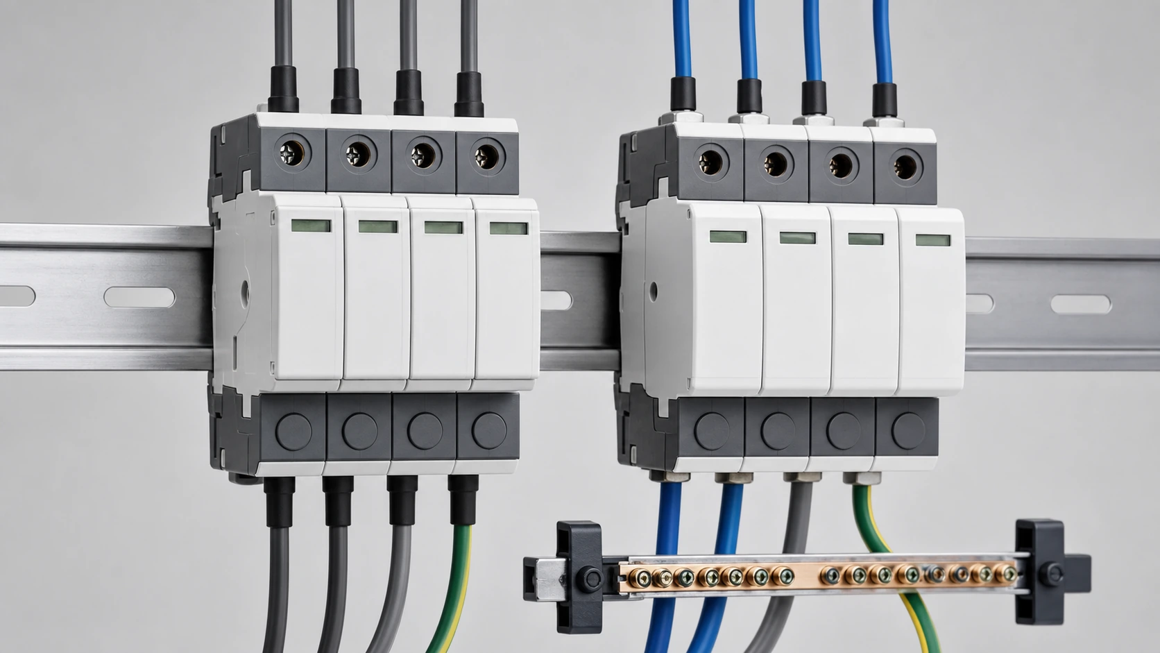
The Quick Answer
A surge protective device diverts transient overvoltage toward earth and then returns to a high-impedance state. On AC, the natural current zero crossing helps extinguish follow current. On DC, follow current can continue until the device interrupts it by design.
- Use an AC SPD on mains distribution boards, incoming panels, motor control centres, AC combiner boxes and inverter AC outputs; IEC 61643-11 is the relevant product standard.
- Use a DC or PV SPD on PV string circuits, combiner boxes, inverter DC inputs, battery buses and energy-storage DC circuits; IEC 61643-31 addresses PV applications.
- Never substitute an AC SPD on a DC circuit. The device may fail to interrupt follow current and can become a sustained thermal fault.
Why DC Surges Behave Differently
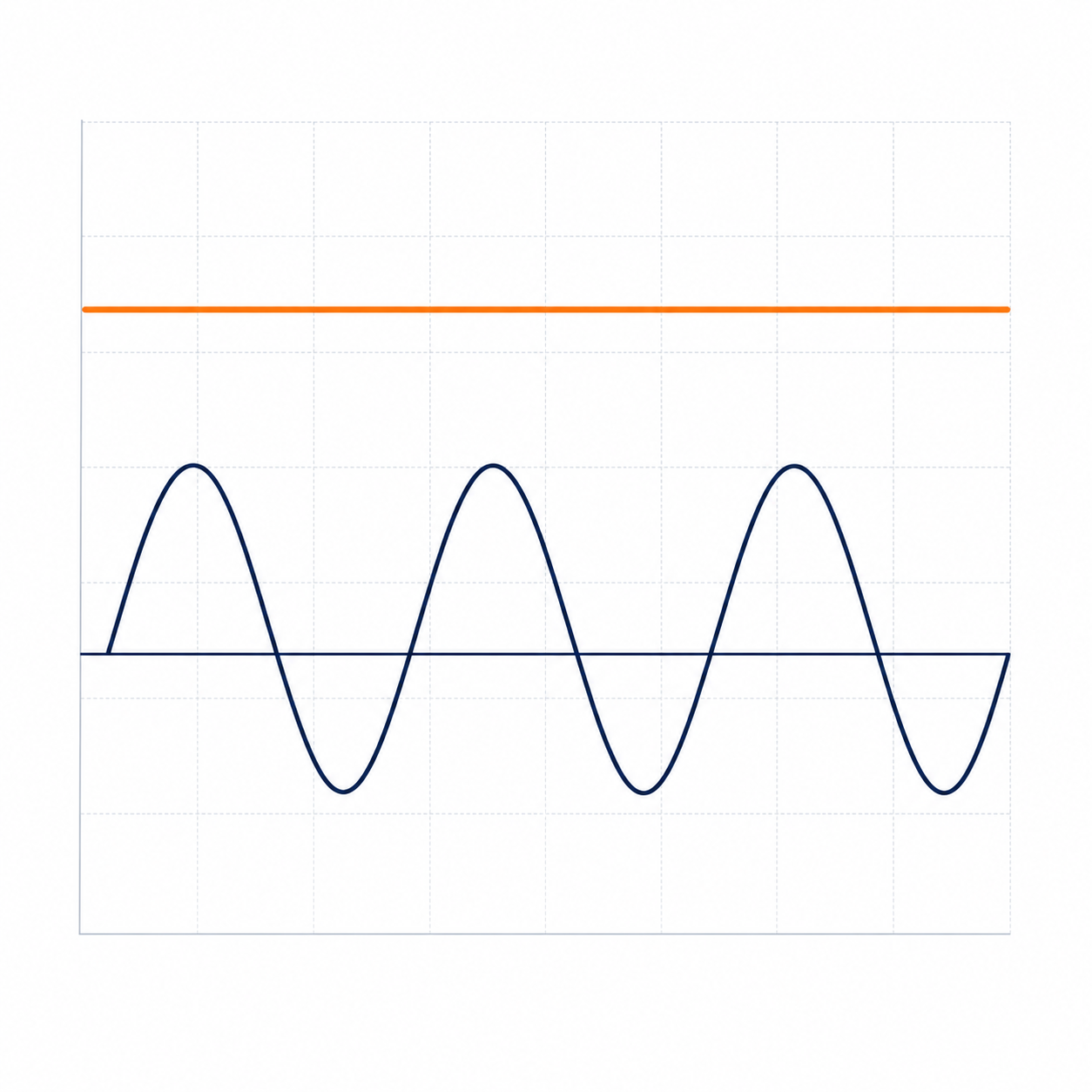
In a 50 Hz AC system, voltage and current pass through zero every 10 ms. If a varistor draws follow current after a surge, the next zero crossing assists interruption. A PV array remains continuously energised during daylight, so a degraded DC SPD must use a qualified DC arc-extinguishing path instead.
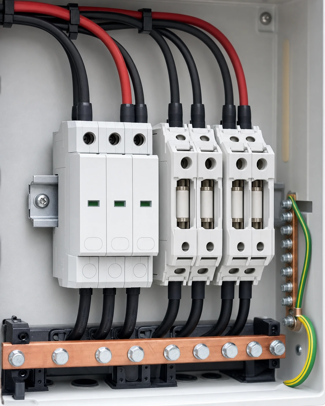
PV SPDs commonly use a Y or 3+0 arrangement: protection branches connect from PV+ and PV− to a midpoint, with a further branch from that midpoint to protective earth. This allows common-mode and differential-mode surge protection while limiting normal leakage.
Standards and Test Classes
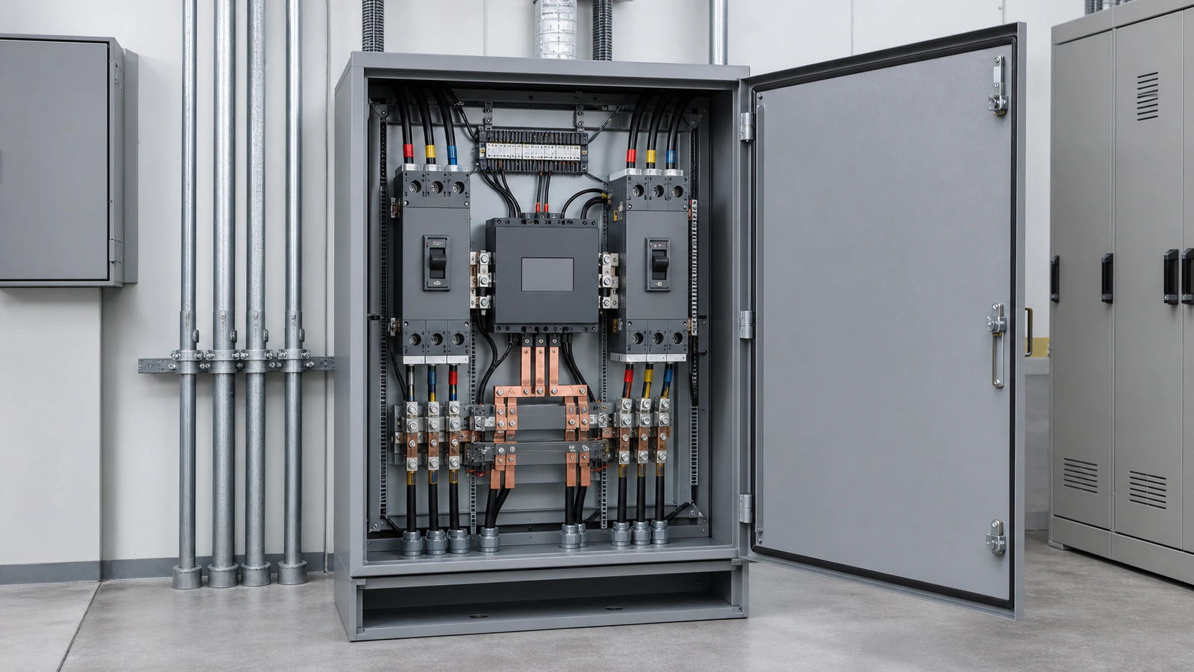
IEC 61643-11 covers AC SPDs and IEC 61643-31 covers SPDs connected to photovoltaic installations. Application and installation decisions also sit within the relevant IEC 61643, IEC 60364 and lightning-protection framework. The assembly context should be checked against IEC 61439 where the SPD is installed inside a switchboard or combiner assembly.
Type 1 devices are tested with the 10/350 μs impulse and rated by Iimp for locations where direct lightning current may enter. Type 2 devices use the 8/20 μs impulse and are commonly applied at distribution boards and combiner boxes. Type 3 devices are coordinated downstream for sensitive terminal equipment.
| Aspect | AC SPD | DC / PV SPD |
|---|---|---|
| Product standard | IEC 61643-11 | IEC 61643-31 |
| Current zero crossing | Present each half cycle | None |
| Follow-current interruption | Assisted by the AC waveform | Must be achieved by device design |
| Typical installation point | Distribution board or AC combiner | PV combiner, inverter DC input or battery bus |
| Backup protection | Fuse or MCB per manufacturer data | gPV fuse or DC-rated device per manufacturer data |
Selecting Uc, In, Imax, Up and SCPD
Uc is the maximum continuous operating voltage. For AC, allow for supply tolerance and the earthing arrangement. For PV DC, base the selection on array open-circuit voltage at the relevant temperature; the source document gives the working rule Uc greater than 1.2 × Uoc(STC).
In is nominal discharge current for repeated 8/20 μs testing, while Imax is a maximum discharge figure for a single event. Up is the voltage protection level that reaches the protected equipment and should be checked against the inverter or load withstand. Iimp is relevant to Type 1 devices. The SCPD is the fuse or breaker specified by the SPD manufacturer; a larger device does not automatically preserve the tested performance.
- Confirm the system voltage and earthing arrangement before choosing Uc.
- Protect both PV polarities where the DC design requires it.
- Check Up against the actual inverter or equipment withstand rather than a generic category value.
- Use the exact backup-protection table supplied for the selected SPD.
Installation, Inspection and Replacement
Keep the live, SPD and earth connections short. The source guide uses a total connecting-lead target below about 0.5 m and warns against long, looped earth conductors because their inductance adds voltage during a fast surge. Coordinate Type 1 and Type 2 devices using the manufacturer’s specified cable length or decoupling method.
SPDs are condition-based protection. Inspect the status indicator during routine maintenance and after significant lightning activity, verify the backup device, and replace a failed plug-in module without disturbing the base where the design permits. PV circuits can remain live in daylight, so isolation, lockout and proving dead are mandatory before work.
Common Selection Mistakes
- Fitting an AC SPD on the DC side because its voltage number appears high enough.
- Choosing Uc from nominal array voltage instead of the open-circuit voltage and temperature condition.
- Ignoring the thermal disconnector, fault indication or specified SCPD.
- Using long or coiled earth leads and assuming the SPD remains maintenance-free.
- Selecting Up above the impulse withstand of the protected inverter or load.
This is general engineering information. The applicable national wiring regulations, lightning-risk assessment, product datasheet and qualified engineer’s design take precedence for a specific installation.
Frequently asked questions
Can I use an AC SPD on a DC circuit if the voltage rating looks high enough?
No. The critical difference is follow-current interruption, not only the voltage number. AC SPDs rely on the current zero crossing, while a DC circuit has none. Use a device tested for the applicable photovoltaic DC standard.
How do I choose Uc for a PV SPD?
Base Uc on the array open-circuit voltage at the relevant temperature rather than nominal operating voltage. The source guide gives Uc greater than 1.2 times Uoc(STC) as a working rule; verify the final value against the design and device data.
What is the difference between Type 1 and Type 2 SPDs?
Type 1 devices use the 10/350 μs impulse and Iimp for locations where direct lightning current may enter. Type 2 devices use the 8/20 μs impulse and In/Imax for distribution and combiner applications.
Why does connecting-lead length matter?
Fast surge current creates inductive voltage across the leads, which adds to the SPD clamping voltage at the equipment. Keep the connections short, avoid loops and follow the manufacturer’s connection arrangement.
How often should an SPD be replaced?
There is no universal fixed interval. Check its status indicator during routine inspections and after significant local lightning activity, then replace it when the device or its backup protection indicates end of life.
Specify the Protection Around the Assembly
Share the system voltage, Uoc(STC), earthing arrangement, exposure level and protection class so the SPD arrangement can be reviewed with the enclosure and the connected equipment.
Request a quoteContinue learning
Explore related technical guidance in Electrical Protection.

Source DOCX: NEUTRON_PUBLISH_ac-spd-vs-dc-spd-key-differences-applications-how-to-choose_v1.0.docx. Technical ratings and any product-specific evidence require confirmation for the quoted configuration.