
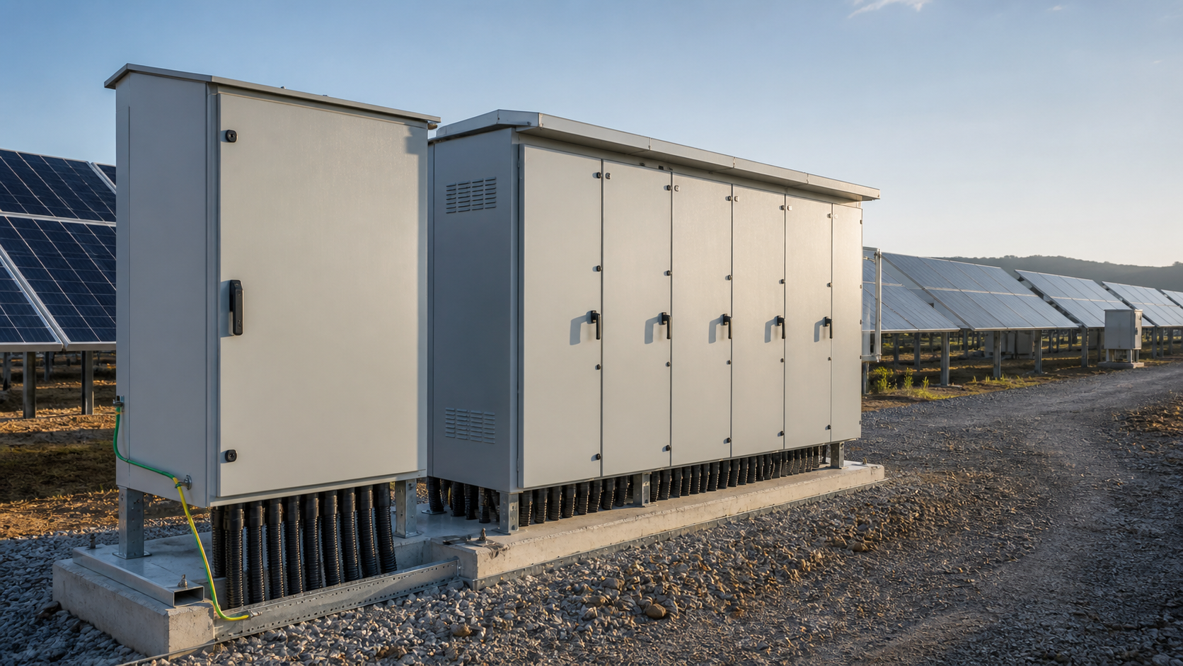
1. What the new PV standards cover (system modeling, parameter testing, grid-connection control)
The updated framework clusters around three technical areas that directly touch BOS design and commissioning:
Together, these shift responsibility toward equipment that can be measured, modeled, and remotely coordinated — not just energized.
- System modeling — the plant must be represented with validated electrical and control models so grid operators can study stability and dispatch behavior before and after connection.
- Parameter testing — key equipment parameters (inverter, protection, and associated BOS characteristics) must be measured and documented rather than assumed.
- Grid-connection operation control — the plant must support agreed control functions such as reactive power response, fault ride-through, and coordinated switching.
2. Why accurate modeling matters for BOS equipment
Grid operators build their system studies on the models they receive. If the BOS layer — combiner boxes, DC protection, and the grid-connected cabinet — is represented with generic or outdated parameters, the model diverges from the real plant and the connection assessment becomes conservative or simply wrong. Accurate modeling reduces the risk of:
BOS suppliers therefore need to supply tested, traceable parameters instead of nominal catalog values.
- Over-specified connection limits that waste capacity.
- Unexpected protection coordination trips during commissioning.
- Rejected or delayed grid-connection applications.
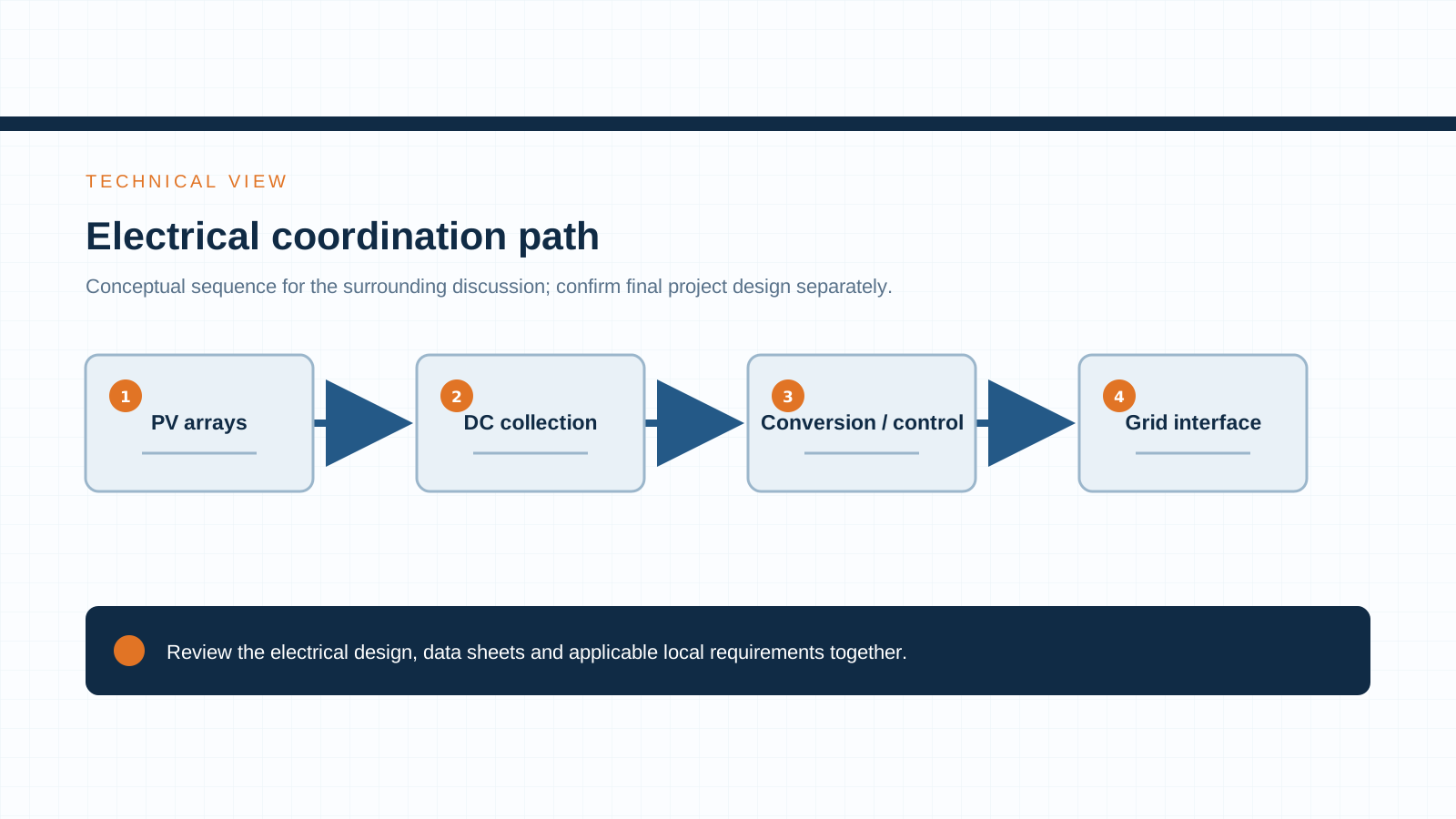
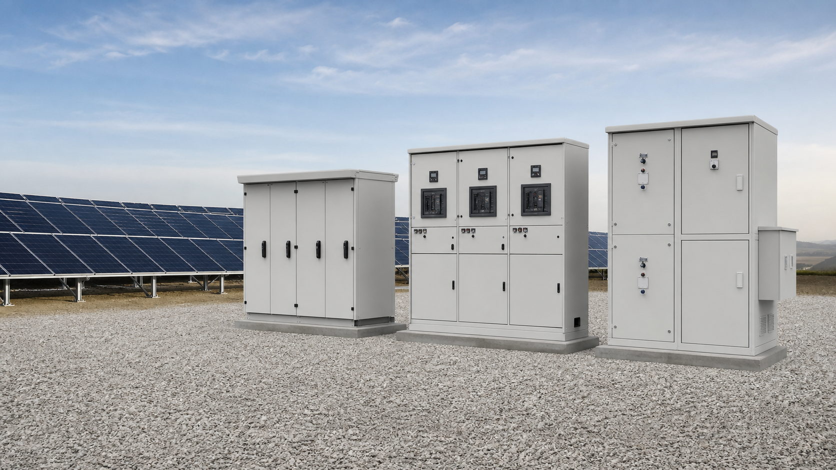
Technical diagram shown at a readable responsive scale.
3. Combiner box and DC protection implications
The combiner box is the first aggregation point where string behavior becomes visible to the plant model. Under the new emphasis on parameter testing and control, combiner boxes should support:
DC protection must be specified for the actual cleared fault levels and the switching sequences the grid-connection control plan expects, not for a generic worst case alone.
- Documented string protection settings (gPV fuse ratings, DC isolation capability) matched to measured module Isc.
- DC surge protection coordinated to the system voltage and the protection level the model assumes.
- Optional string-level monitoring so measured operating data can validate the modeled behavior.
4. Grid-connected cabinet and LV switchgear implications
The grid-connected cabinet and the low-voltage switchgear behind the inverter are where plant-side control meets the network. The new control requirements raise the bar on:
Equipment that cannot demonstrate its rated performance under the modeled duty will struggle to pass connection acceptance.
- Switching and isolation rated for the real connection duty cycle, including frequent coordinated switching.
- LV switchgear assemblies built and verified to IEC 61439 so the cabinet behaves as modeled under load and fault conditions.
- Reactive power and voltage support hardware that the operation control function can command without exceeding assembly ratings.
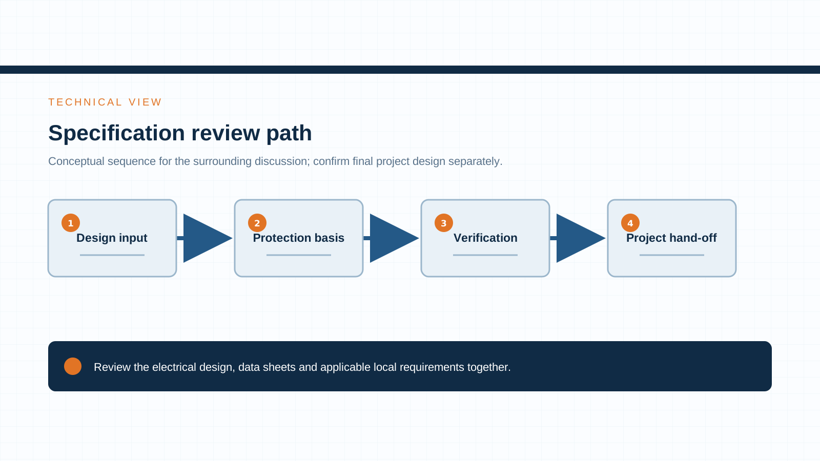
Technical diagram shown at a readable responsive scale.
5. Monitoring and data hand-off for grid dispatch
Modeling and operation control both depend on data. A practical implication for BOS is the need for a clean data hand-off path from the field to the dispatch and monitoring system:
Treating monitoring as an afterthought undermines the very control functions the standards now expect.
- Combiner box and cabinet status (protection state, isolation, alarms) should be available to the plant controller.
- Measured parameters used in commissioning should feed back into the model for verification.
- Event and fault records must be timestamped and retrievable so the operator can confirm control performance.
6. Compliance checklist for equipment suppliers
To align with the new connection expectations, BOS suppliers can prepare the following before a grid-connection application:
- Provide measured, not assumed, equipment parameters for modeling.
- Confirm protection coordination across combiner box, DC protection, and grid-connected cabinet.
- Demonstrate LV switchgear compliance to IEC 61439 with verified ratings.
- Document monitoring points and the data hand-off to the plant controller.
- State the supported control functions (reactive power, ride-through, switching) explicitly.
- Keep a parameter dossier that commissioning tests can be checked against.
7. Standards references
The connection and equipment requirements draw on a mix of national and international documents. For BOS design and verification, the most relevant include:
Referencing these on the datasheet and in the parameter dossier shows the equipment was built to a verifiable basis.
- GB/T PV series — Chinese national standards covering PV generation system modeling, testing, and grid-connection requirements.
- IEC 61727 — utility-interconnected PV system — interface characteristics.
- IEC 62116 — test procedure for islanding prevention and anti-islanding protection of grid-connected PV inverters.
- IEC 61439 — low-voltage switchgear and controlgear assemblies, the basis for verifying cabinet and switchgear construction.
8. What to ask your combiner-box / switchgear supplier
When you issue an enquiry for a project under the new connection rules, the questions that surface the real compliance gap are:
NEUTRON reviews the application context and prepares a configuration discussion around your project requirements, covering combiner equipment, DC control protection, and low-voltage switchgear rated for modern PV connection duties.
- Can you provide measured equipment parameters for system modeling, not just nameplate values?
- How is protection coordinated across the combiner box, DC protection, and grid-connected cabinet?
- Is the LV switchgear verified to IEC 61439 for the actual duty cycle?
- Which monitoring points are exposed to the plant controller for dispatch and verification?
- Which grid-connection control functions does the equipment support out of the box?
This is general technical guidance. Final ratings, standard editions, protection coordination and compliance evidence must be confirmed for the actual project and applicable local requirements.
Frequently asked questions
What do the new PV grid-connection standards require?
They require validated system modeling of the plant, measured equipment parameter testing, and support for defined grid-connection operation control functions such as reactive power response and fault ride-through. The aim is a consistent modeling and control basis for large-scale PV integration.
How do grid-connection standards affect combiner box design?
They push combiner boxes toward documented, tested protection settings, coordinated DC surge protection, and — where useful — string-level monitoring so measured data can validate the plant model used in the connection assessment.
Which standards apply to PV BOS equipment?
The GB/T PV series covers national modeling, testing, and grid-connection requirements, while IEC 61727, IEC 62116, and IEC 61439 govern interface characteristics, anti-islanding testing, and low-voltage switchgear assemblies respectively.
Why is system modeling important for PV integration?
Grid operators study stability and dispatch using the models they receive. If the BOS layer is represented with generic or outdated parameters, the model diverges from the real plant, leading to conservative limits, protection trips, or delayed connection approval.
Bring the project inputs to the first review.
NEUTRON reviews the application context and prepares a configuration discussion around project requirements and the applicable document package.
Discuss a projectContinue learning
Explore related technical guidance in Solar PV.
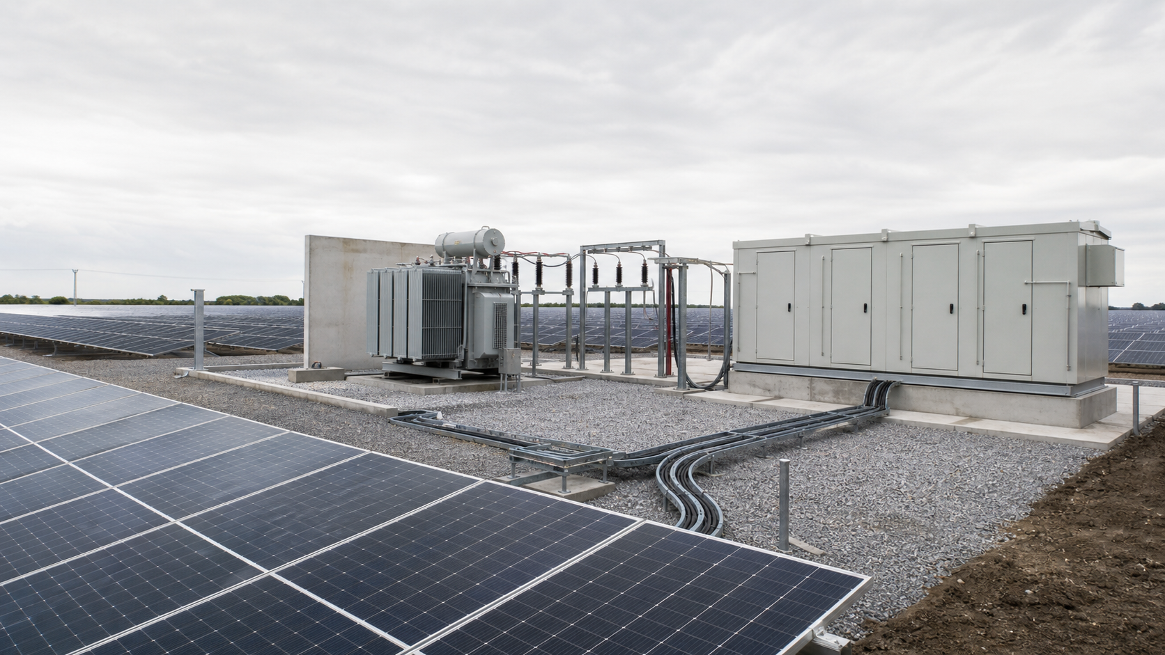

Technical note: confirm the applicable standard edition, project design basis, local requirements and evidence package before final equipment selection or release.