
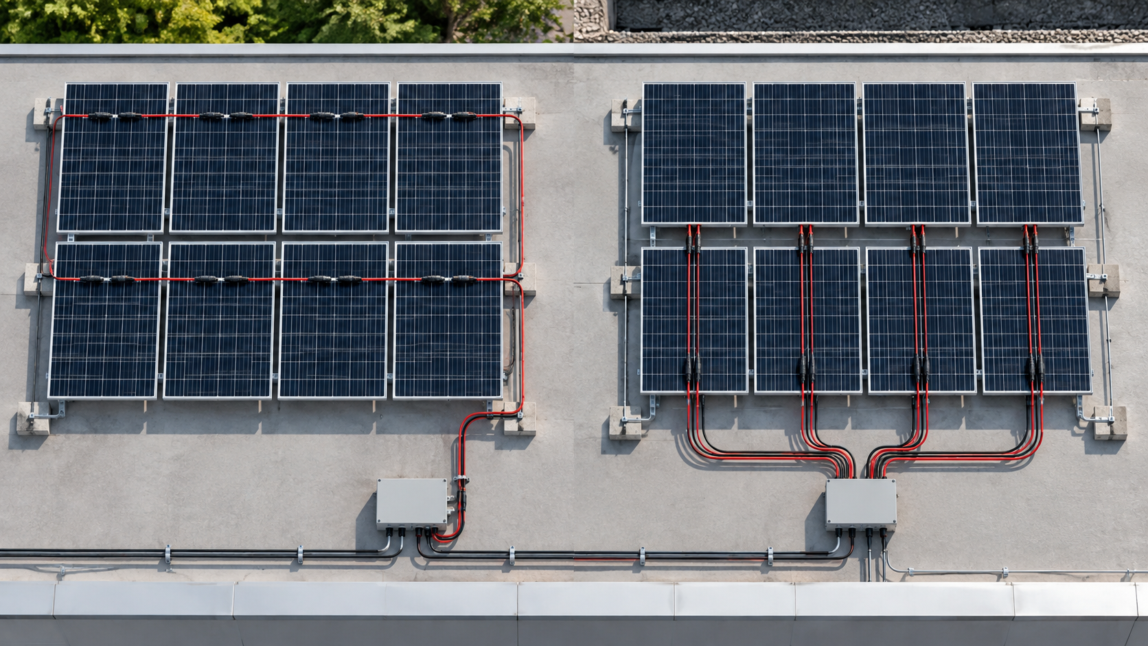
Series vs parallel at a glance
In series, panels connect positive to negative, adding their voltages while current stays equal to one panel. In parallel, positives join positives and negatives join negatives, adding current while voltage stays at one panel's level.
The choice changes every number downstream: string voltage drives inverter limits and insulation, while string current drives fuse and conductor sizing. The combiner box is where these wired groups are collected and protected.
Technical diagram shown at a readable responsive scale.
Voltage and current formulas
Series: V_string = n x V_panel, I_string = I_panel. Parallel: V_group = V_panel, I_group = n x I_panel. These simple sums are the foundation of all PV array design.
A 10-panel series string at 40 V and 10 A becomes 400 V at 10 A; the same 10 panels in parallel become 40 V at 100 A. The power is similar, but the electrical demands on wiring and protection are completely different.
When to wire series
Series wiring is the default for grid-tied arrays because it raises voltage toward the inverter's MPPT window and keeps current low, allowing thinner, cheaper DC cabling and smaller fuses.
Low current also means less heating in the combiner box busbar. Most rooftop and utility systems therefore use series strings as their base building block.
Technical diagram shown at a readable responsive scale.
When to wire parallel
Parallel groups are used when voltage must stay low — for example small 12 V or 24 V off-grid systems — or when panels face different conditions and you want to add current rather than stack voltage.
Parallel wiring raises current fast, so the fuses, connectors and busbar must be sized for the summed current. NEUTRON DC protection handles these higher-current groups with appropriately rated parts.
Combined series-parallel arrays
Large arrays use series-parallel: several series strings wired in parallel. You get the voltage of one string and the current of all strings combined — the standard shape for kW-scale systems.
Each series string in the group is still its own protected unit with a gPV fuse, then the combiner box joins them into one DC output feeding the inverter.
Worked example
Take eight 400 W panels, 40 V and 10 A. Four in series give 160 V at 10 A; two such strings in parallel give 160 V at 20 A. Total 3200 W from a compact, low-current DC feed.
Each 160 V string gets its own fuse in the combiner box; the box's output busbar carries the combined 20 A. The inverter sees a clean 160 V DC input well inside its window.
Protection for each topology
Series strings need a gPV fuse per string so a fault cannot be fed by neighbours, plus a disconnect for isolation. Parallel groups need fuses sized to the higher combined current and careful connector matching.
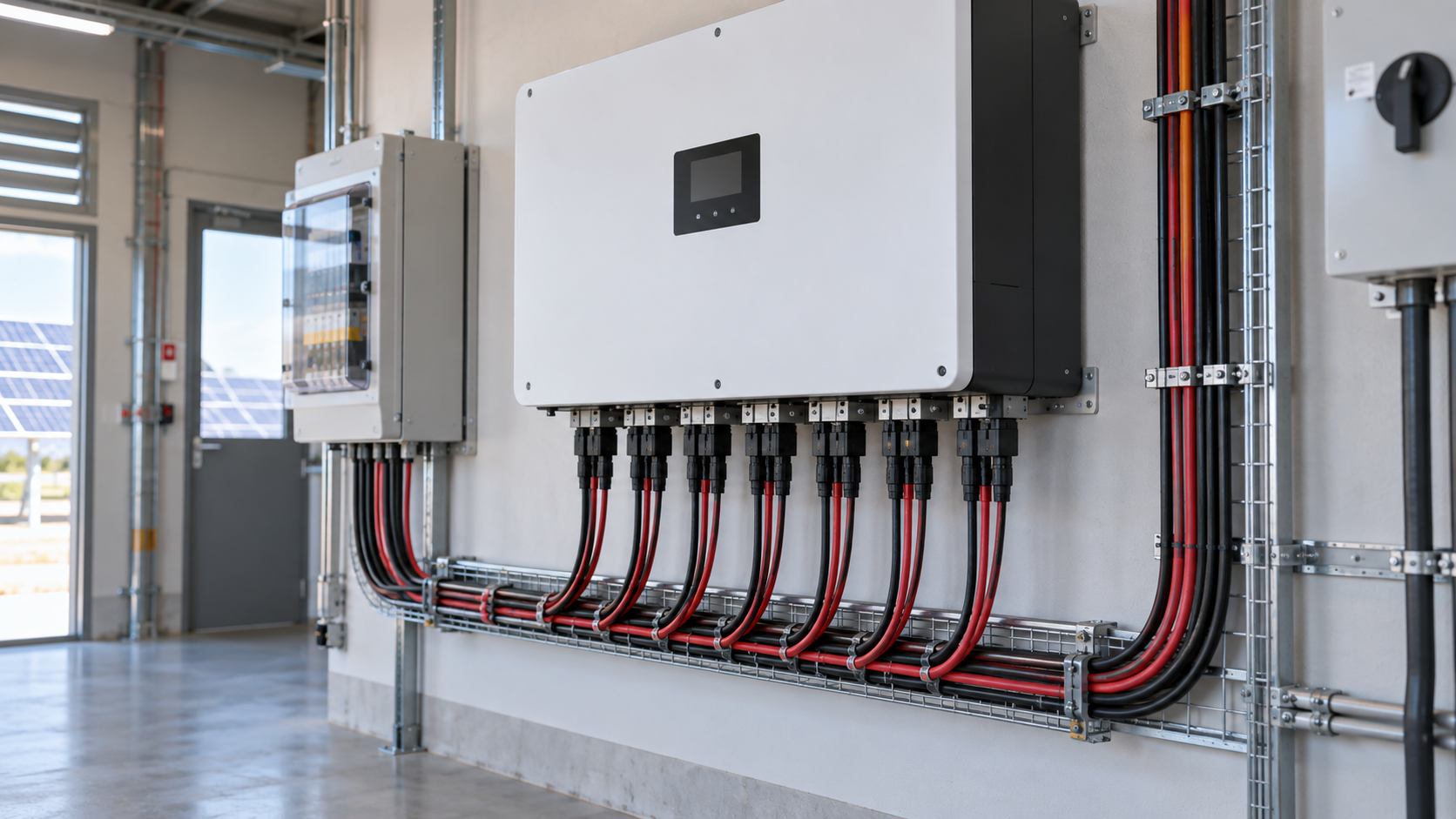
The combiner box unifies this: fused string inputs, a main DC disconnect, and optional surge protection, all rated for the system voltage and the summed current the topology produces.
Bringing strings into the combiner box
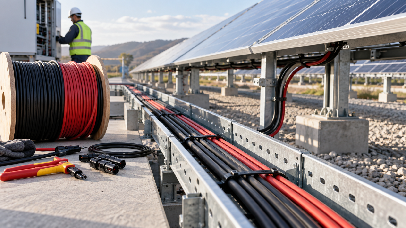
Whatever the wiring, strings arrive at the combiner box through MC4 inputs, one fused circuit each. The box aggregates them, provides isolation, and sends a single protected DC feed to the inverter or charge controller.
NEUTRON combiner boxes are designed around your series-parallel plan: correct input count, fuse rating per string, and an output busbar sized for the combined current your wiring produces.
This is general technical guidance. Confirm final ratings, protection coordination, installation and applicable local requirements against current standards, manufacturer documentation and the approved project design.
Frequently asked questions
Series or parallel for my array?
Use series for grid-tied systems to reach the inverter's voltage window with low current. Use parallel when voltage must stay low (small off-grid) or when adding current is the goal. Large arrays combine both.
Does series raise voltage or current?
Series raises voltage and keeps current at the level of a single panel. That is why it allows thinner cabling and smaller fuses than parallel wiring of the same panels.
Can I mix series and parallel?
Yes, through series-parallel configuration: build series strings, then join them in parallel. Each string still needs its own fuse in the combiner box before the combined output.
How does wiring affect fuse sizing?
Series strings are fused at roughly 1.25x the string Isc; parallel groups carry summed current so fuses and busbars must match the higher total. The combiner box applies the right rating per topology.
Discuss your PV requirement
Share the system voltage, string arrangement, inverter interface and installation environment. NEUTRON can review the equipment configuration around your project documentation.
Discuss a projectContinue learning
Explore related technical guidance in Solar PV.
Published from the approved Period 06 source package. Technical values and final design decisions must be verified against the current applicable standard, manufacturer documentation and approved project design.