
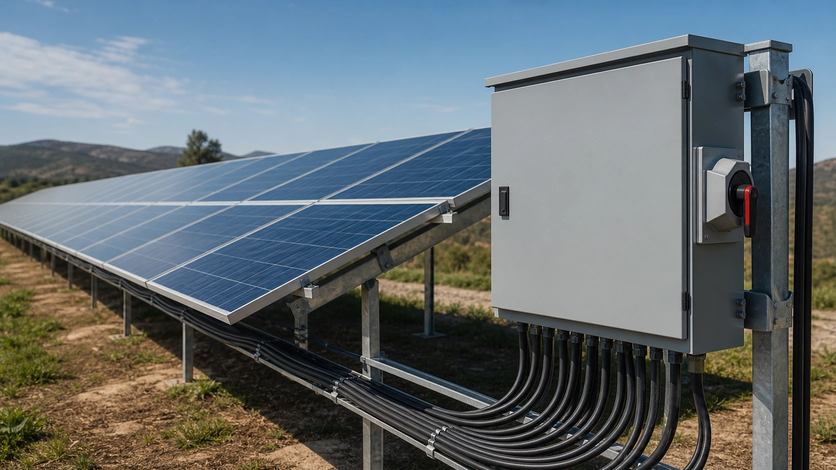
Three devices, three jobs
Follow the current path: cells are connected inside the module junction box; modules are connected into strings; multiple strings return to a field combiner box; the combined output feeds the inverter; and a DC breaker or isolator provides a service point. Each device answers a different engineering question.
- Junction box: module-level termination and bypass-diode function.
- Combiner box: field-level string aggregation, protection and optional monitoring.
- DC breaker or isolator: switching and isolation for the DC circuit.
What a PV module junction box does
The junction box is normally factory-bonded to the rear of each module. It terminates the cell sub-string ribbons, houses bypass diodes and provides the module's sealed cable and connector interface.
- It is typically an IP67 or IP68 potted module component.
- It does not provide array overcurrent protection or a field isolation point.
- A bypass-diode problem may appear as a hot spot or underperforming string and can require infrared or IV-curve investigation.
What a PV combiner box does
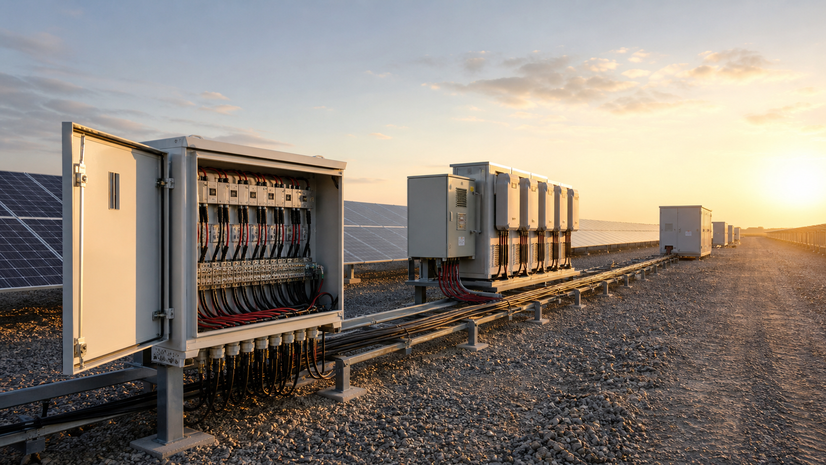
A combiner box is the first field-engineered protection point for many PV arrays. It parallels several strings onto positive and negative buses and may include per-string fuses, DC surge protection, a load-break isolator and monitoring interfaces.
- String fuses are selected from Isc and the module's maximum series-fuse rating.
- Type 2 DC SPDs need a continuous operating voltage compatible with the cold-weather Uoc.
- The enclosure and glands must be suitable for the complete outdoor environment.
- Monitoring can include per-channel current, bus voltage, SPD status and communications where required.
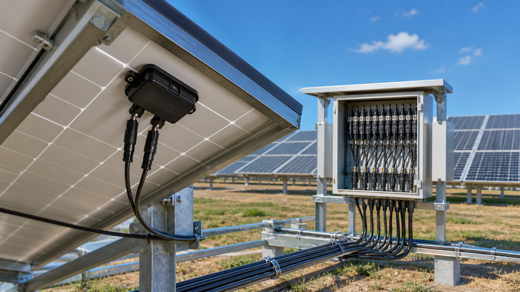
DC circuit breakers and load-break isolators
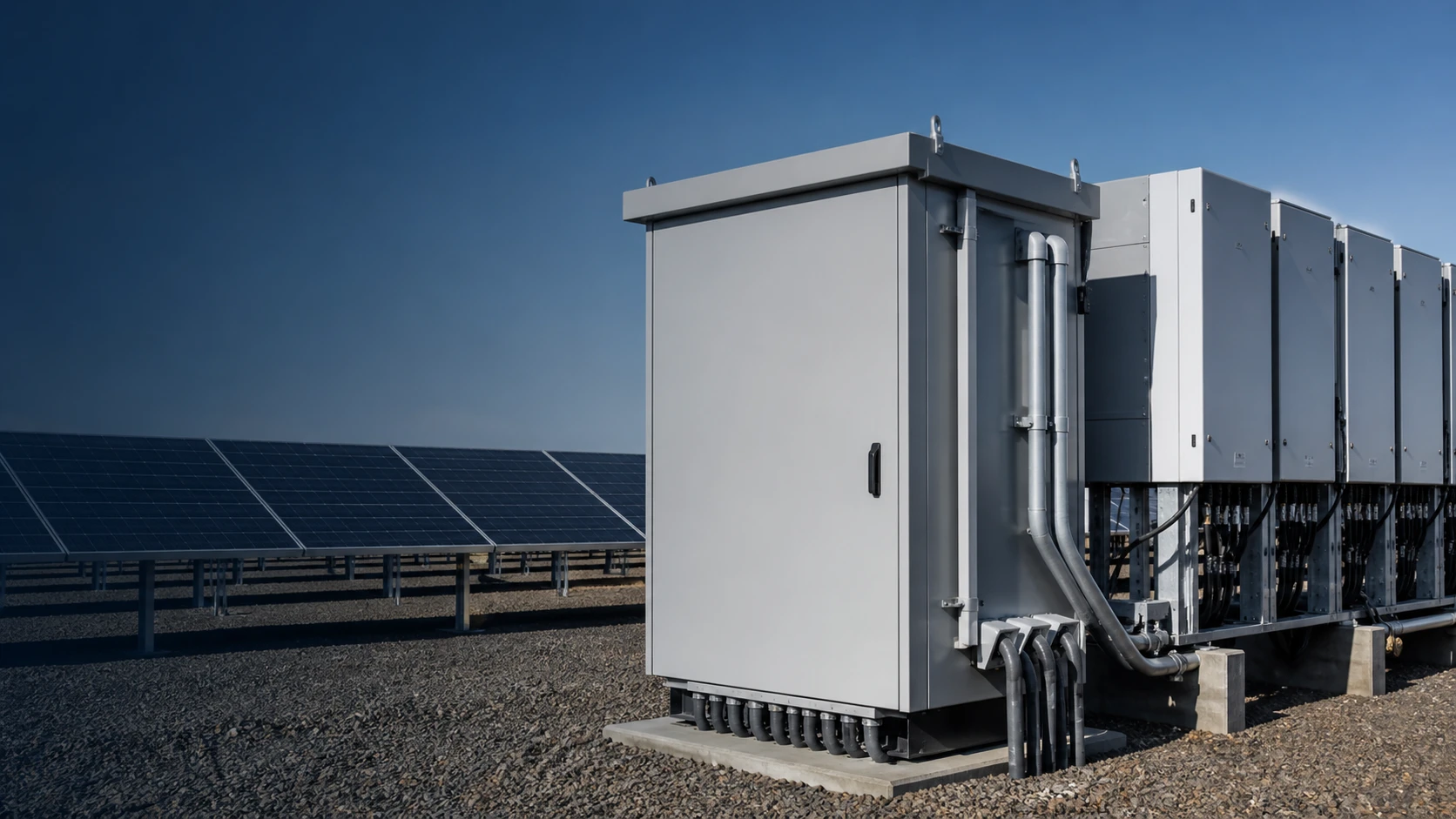
A DC breaker can be re-closed after inspection and provides a visible, lockable isolation point. In a PV plant it may appear at the combiner output, the inverter DC input or a larger recombiner or DC distribution level.
- Check the DC breaking capacity at the actual array voltage, not the adjacent AC rating.
- A 1000 V and a 1500 V array may require different pole arrangements and series-pole coordination.
- Never operate a fuse holder or isolator under load unless it is specifically rated for that duty.
Side-by-side comparison
The functional boundary is clearer when the devices are compared by position and protection scope.
| Attribute | Module junction box | PV combiner box | DC breaker / isolator |
|---|---|---|---|
| Position | Rear of each module | Between strings and inverter | Combiner output or inverter input |
| Primary function | Terminate cell sub-strings | Parallel strings on a DC bus | Switch and isolate the DC circuit |
| Overcurrent protection | None | Per-string fuses where required | Thermal-magnetic or electronic trip |
| Surge protection | None | DC SPD where specified | Not inherent |
| Field serviceable | Usually no | Fuses, SPD and monitoring can be serviced | Yes, with safe isolation |
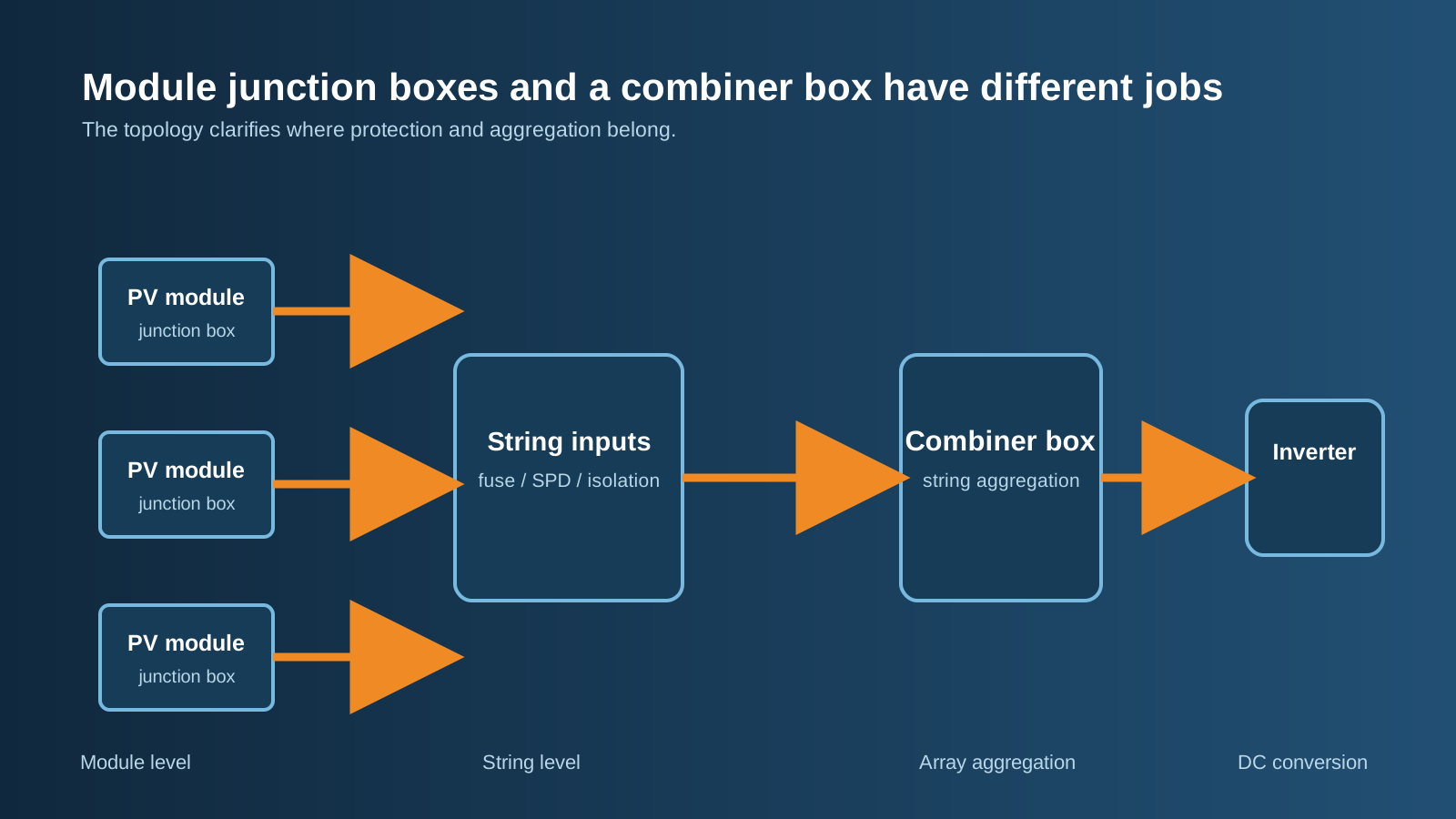
Technical diagram shown at a readable responsive scale.
Sizing rules that keep the array protected
Use module data and the coldest expected site temperature rather than nameplate averages.
- Correct Uoc for low temperature and keep it below the inverter and isolator voltage class.
- Use Isc and the project continuous-duty factor for string-fuse and output-current decisions.
- Consider the number of parallel strings because reverse fault current rises with healthy parallel strings.
- Size the combined output isolator and cable from the sum of string currents and the design factor.
- Select SPD Uc so normal cold-weather voltage does not drive the varistor into conduction.
Factory acceptance checks to request
A routine factory inspection record should identify the exact assembly and show that the protection, insulation, earth continuity, clearance, monitoring and sealing checks were completed. Ask for the same evidence when comparing suppliers.
- Insulation resistance and earth continuity.
- Clearance and creepage review.
- Fuse and SPD ratings, status indication and disconnector arrangement.
- Monitoring accuracy where monitoring is part of the order.
- Enclosure sealing and cable-gland verification.
Common mistakes and safety limits
DC arcs can sustain. Open the output isolator, confirm zero current and follow the approved procedure before accessing fuse carriers. Do not reuse AC-rated components on the DC side, and inspect SPD status during scheduled maintenance.
- Confirm the enclosure protection and corrosion resistance for desert, coastal or chemically aggressive sites.
- Review local requirements for array earthing, arc-fault detection and rapid shutdown.
- Have the final DC schematic and factory records reviewed by the responsible engineer or inspector.
This is general PV application guidance, not a substitute for the module and inverter manuals, local code, product data sheets or a qualified engineer's design review.
Frequently asked questions
Is a solar junction box the same as a combiner box?
No. The junction box is attached to each module and manages its internal cell sub-strings and bypass diodes. The combiner box is a field assembly that parallels several strings and can add fuses, SPD and isolation.
Do I always need string fuses?
Not always. The need depends on the number of parallel strings, reverse fault current, module maximum series-fuse rating and the approved design.
Can I use an AC circuit breaker on the DC side?
No, unless the device has a declared DC rating and breaking capacity for the actual voltage and duty. An AC-only rating does not establish PV suitability.
What IP rating should a PV combiner box have?
Indoor and outdoor requirements differ. The final IP class must be verified for the complete assembly with glands and covers, and must match dust, water, salt and corrosion exposure.
What documents should a combiner-box supplier provide?
Request the exact data sheet, wiring diagram, component schedule and routine inspection evidence for insulation, earth continuity, clearances, fuse and SPD ratings, monitoring and enclosure sealing.
Review the PV DC Arrangement
Send the string count, Uoc, Isc, inverter inputs, site conditions and destination market so the combiner, fuses, SPD, isolator and enclosure can be reviewed as one coordinated system.
Request a quoteContinue learning
Explore related technical guidance in Solar PV.
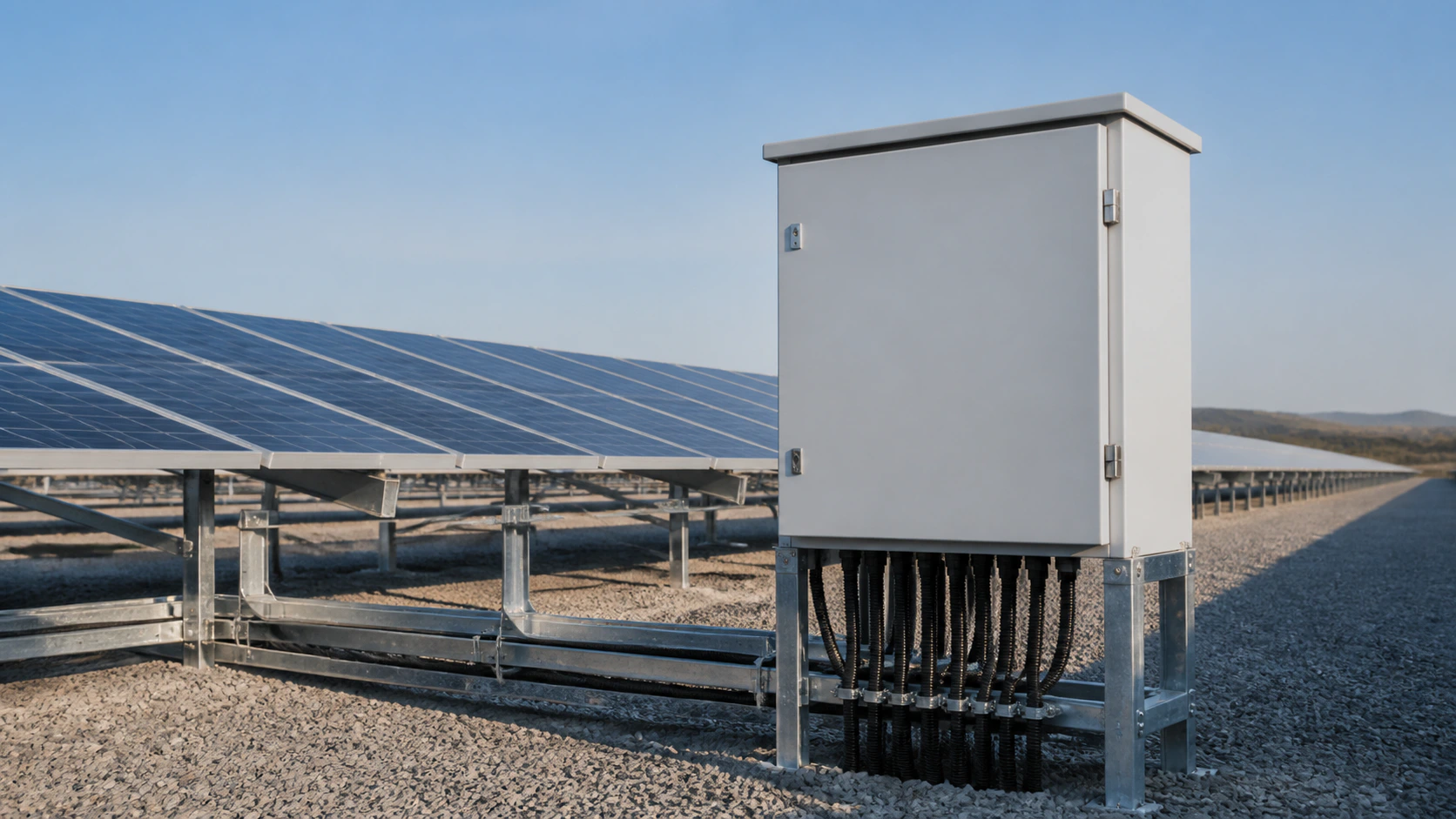
Technical note: DC ratings, fuse and SPD coordination, enclosure class and compliance evidence must be confirmed against the actual PV project.