
1. The Fundamental Difference: Position in PV Topology
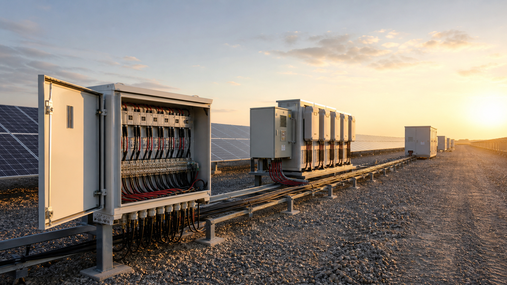
Every photovoltaic plant converts energy once, in the inverter. Everything upstream of that conversion is a DC problem; everything downstream is an AC problem. The two combiner box families map directly onto that split.
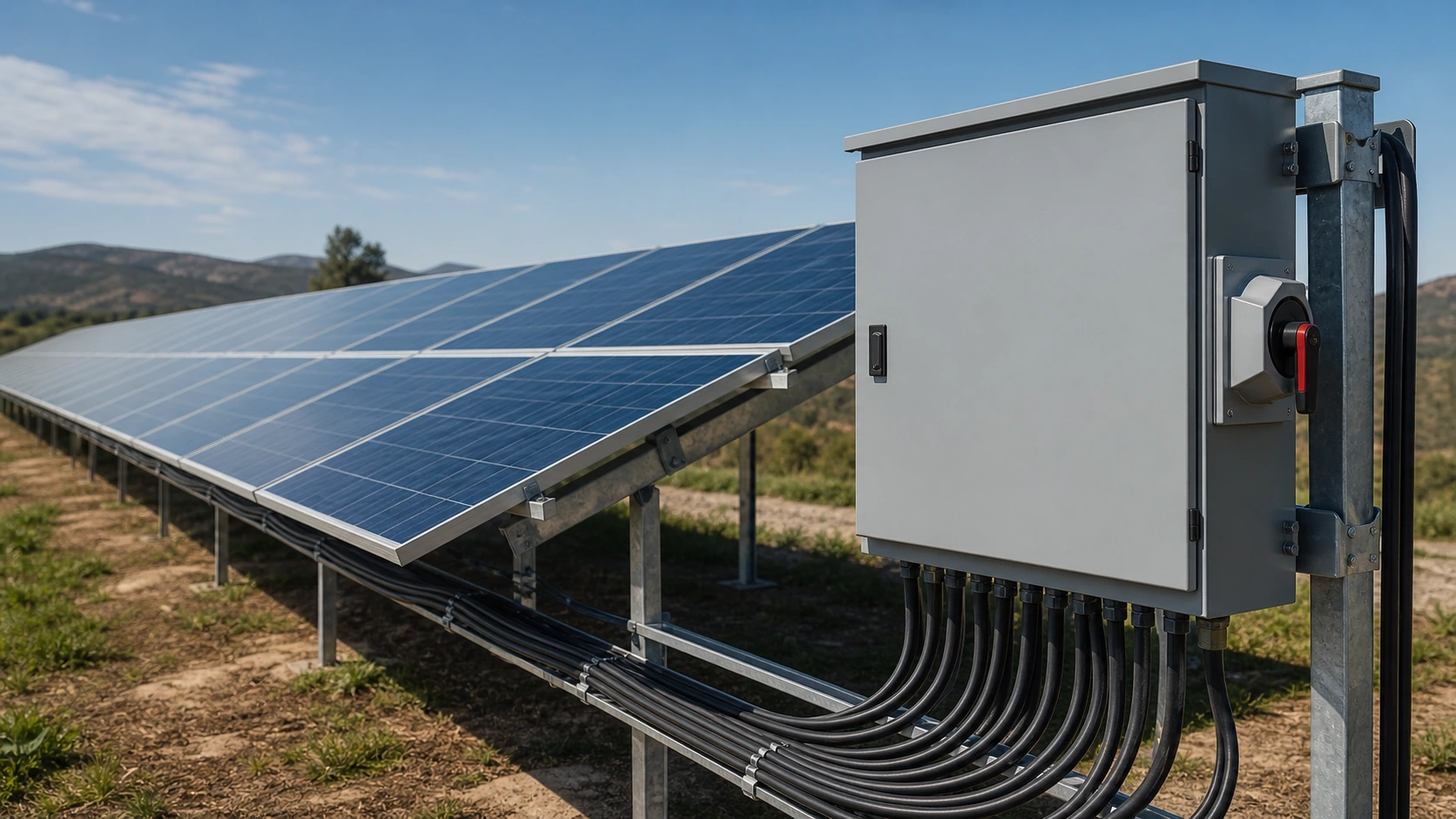
Upstream (DC side): modules are wired in series into strings. Several strings are paralleled in a DC combiner box so that one cable, not twenty, runs to the inverter. Current sums; voltage stays at the string value. Protection has to interrupt a fault current that never crosses zero.
Downstream (AC side): each inverter produces three-phase AC at 400 V, 415 V or 690 V. An AC combiner box parallels those feeds onto a common busbar and sends one feeder to the transformer, the grid-connected cabinet or the main low-voltage board. Protection is conventional AC practice: moulded case breakers, AC surge protective devices, and where required, metering.
Confusing the two is not a paperwork error. A device rated 1000 V AC may be rated only 500 V DC or not rated for DC at all, and it will fail to clear a DC fault safely.
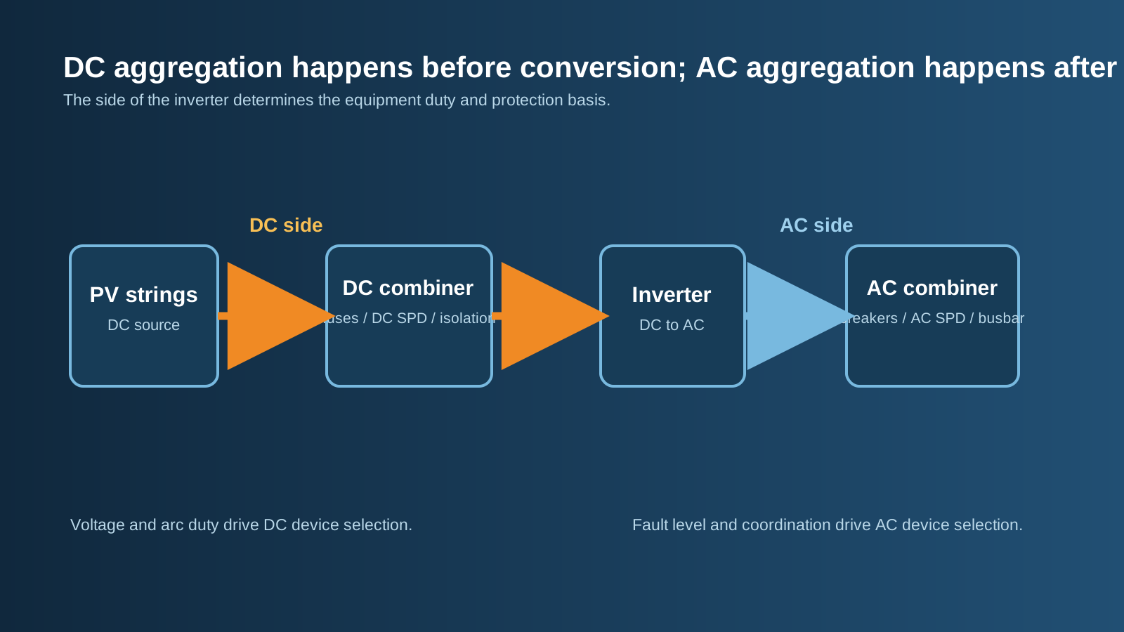
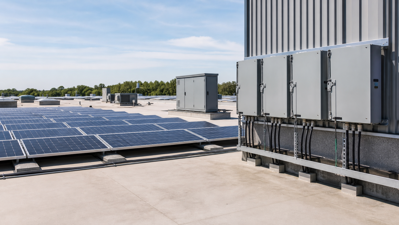
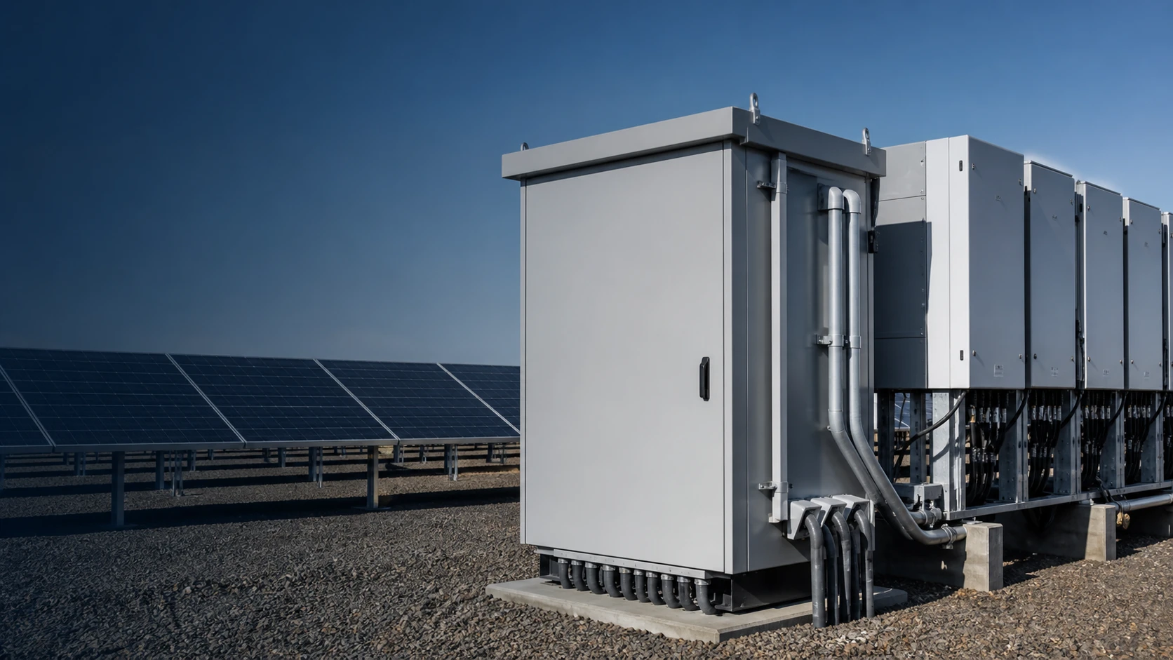
Technical diagram shown at a readable responsive scale.
2. The DC Combiner Box: Pre-Inverter Consolidation
A NEUTRON PV DC combiner box handles the harshest electrical duty in the plant. Standard configurations run from 1 in / 1 out up to 16 in / 1 out, at 500 V, 1000 V or 1500 V DC, in outdoor enclosures rated IP54 or IP65.
The design constraint that shapes everything is the DC arc. Without a zero crossing, an arc drawn across opening contacts is self-sustaining until the gap is long enough or the arc chute cools it. That is why fuse holders in a DC box carry a permanent instruction never to operate under load, and why isolation is always done with the output breaker first.
- Per-string gPV fuses to IEC 60269-6, on both polarities, rated at 1.25 × Isc or higher.
- Type 2 DC surge protective device to IEC 61643-31, In (8/20 µs) of at least 10 kA, with Uc above 1.2 × Uoc(STC), an internal disconnector and a visible status window.
- Copper busbar sized for the summed string current.
- DC-rated load-break switch or moulded case circuit breaker on the output.
- Optional monitoring: per-channel current and busbar voltage to ±1 % of full scale over RS485 / Modbus RTU.
3. The AC Combiner Box: Post-Inverter Aggregation
An AC combiner box is closer in character to a compact low-voltage distribution board. NEUTRON builds AC combiner boxes to IEC 61439 at up to 690 V AC, with an incoming way for each inverter behind its own moulded case circuit breaker, a common three-phase busbar, and a single outgoing feeder.
The value is operational. When each inverter has a dedicated breaker, a technician can isolate one machine for firmware work or an IGBT replacement while the rest of the plant keeps exporting. Without that box, isolating a single inverter usually means dropping the whole feeder.
Typical content: 3-pole or 4-pole MCCBs sized to inverter continuous output current, a Type 2 AC SPD to IEC 61643-11, optional current transformers and an energy meter for per-inverter yield accounting, and RS485 communication. Enclosures follow the same environmental logic as the DC side — IP54 for sheltered outdoor positions, IP65 where sand, salt or washdown is expected.
4. Technical Architecture Side by Side
Read the table as a rule of thumb rather than a catalogue. The one line that never bends is arc behaviour, and it is the reason component substitution between the two families is prohibited.
| Parameter | DC combiner box | AC combiner box |
|---|---|---|
| Position in system | Between modules and inverter | Between inverters and grid interface |
| Typical voltage class | 500 / 1000 / 1500 V DC | 400 / 415 / 690 V AC |
| Input count | 1 to 16 strings (higher on recombiners) | 2 to 12 inverter feeds |
| Per-input protection | gPV fuse, IEC 60269-6, ≥1.25 × Isc | MCCB sized to inverter output current |
| Surge protection | DC Type 2, IEC 61643-31, In ≥10 kA | AC Type 2, IEC 61643-11 |
| Isolation device | DC load-break switch / DC MCCB | AC MCCB, optional motorised operation |
| Arc behaviour | No current zero — sustained arc risk | Self-extinguishes at zero crossing |
| Governing assembly standard | IEC 61439, IEC 62548 array design | IEC 61439-2 |
| Typical enclosure | IP54 / IP65 outdoor, powder-coated steel | IP54 / IP65, wall or floor mounted |
| Monitoring | String current deviation, SPD status | Per-inverter energy, breaker status |
5. Fuses, Breakers and SPD Type Selection
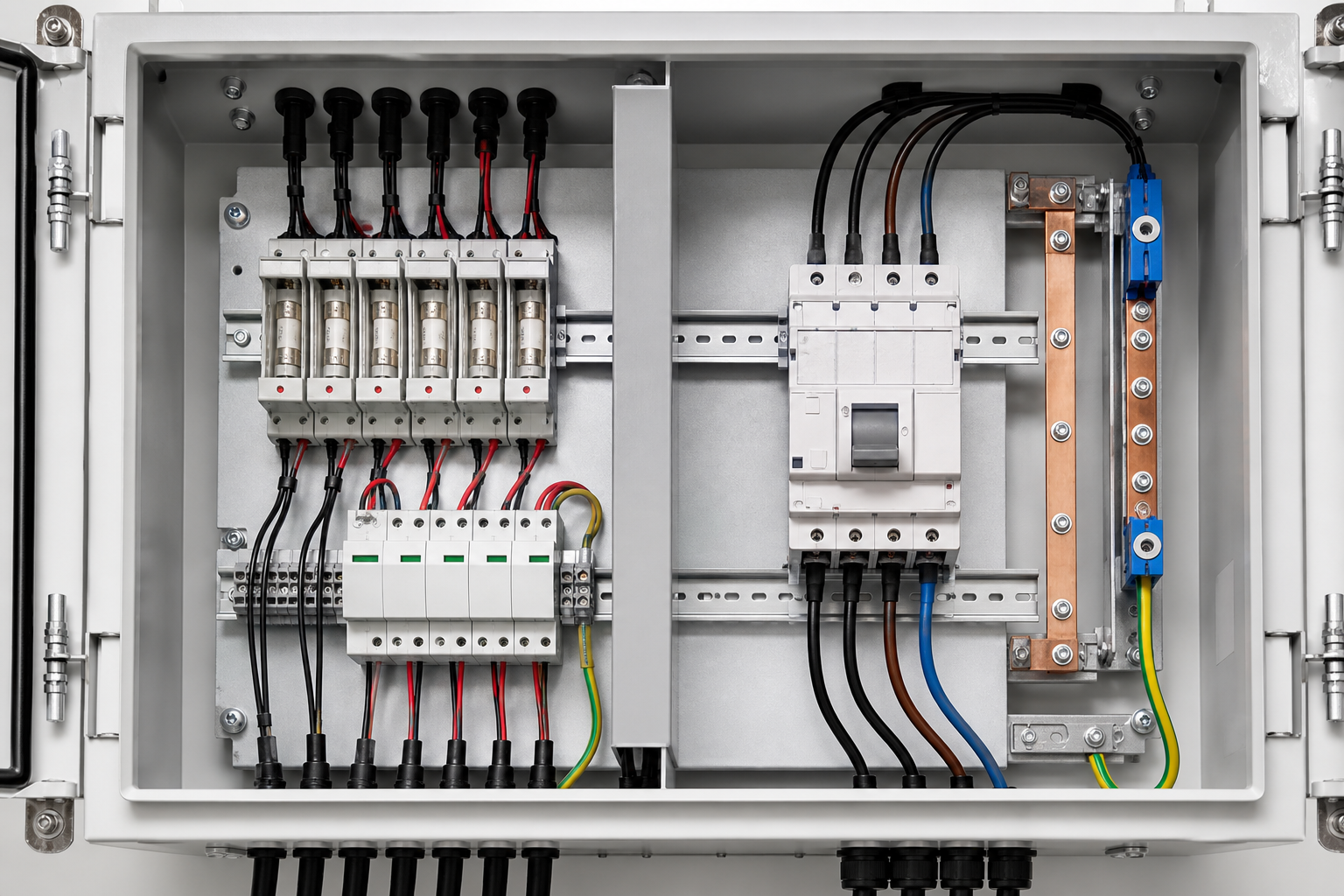
Why fuses on the DC side? A string produces a limited current — typically 10 A to 20 A — so a faulted string is not fed by its own generation but by the other strings in parallel with it. A compact, fast gPV fuse clears that reverse feed cleanly, costs little per way, and lets a 16-string box stay physically small. Breakers rated for 1000 V or 1500 V DC exist, but they are larger and more expensive per pole, so they are normally used for the box output rather than per string.
Why breakers on the AC side? Inverter feeds carry high continuous current, the fault current comes from the grid, and operators need repeatable switching for maintenance. A moulded case circuit breaker gives both protection and a switching duty rated for thousands of operations.
SPD selection follows the lightning protection zone concept. Use a Type 1 device where a structure has an external lightning protection system and direct strike current can be conducted into the installation. Use Type 2 as the standard in combiner boxes and distribution boards. Use Type 3 only as fine protection close to sensitive equipment. On the DC side the device must be declared to IEC 61643-31; an AC protector installed in a DC circuit cannot clear its own follow-current and becomes a fire risk.
6. Matching Combiners to Inverter Topology
Central inverters, utility-scale. A 3 MW block feeding one or two central machines needs aggregation on the DC side, usually in two stages: field combiner boxes with 8 to 16 strings each, then recombiner boxes that parallel the combiner outputs at 250 A to 630 A per input. AC aggregation happens in the grid-connected cabinet or the LV side of the step-up transformer.
String inverters, commercial and industrial. Modern string inverters accept six to twelve MPPT inputs directly, so field DC combining is often unnecessary — the inverter is the combiner. What the plant needs instead is an AC combiner box to group eight or ten inverters onto one feeder. Buying DC boxes for a string-inverter plant is the most common overspecification we see in tender documents.
Hybrid and mixed layouts. Rooftop C&I sites with long DC cable runs sometimes still use small 3-in or 4-in DC boxes to reduce cable count across a roof, then an AC box in the plant room. That is a legitimate design as long as each box is rated for its own side of the inverter.
7. Arc Fault Risk, Safety and Procurement Checks
DC arc faults are the dominant fire mechanism in PV balance of system. They start at a loose terminal, a corroded MC4 connector or a cracked cable, and they persist because the array keeps supplying current while the sun is up. Three controls reduce the risk more than anything else: correct torque at every termination, verified sealing at every entry, and annual thermographic inspection under load.
- Confirm the DC voltage class against the coldest-day corrected Uoc, not the STC figure.
- Confirm SPD type, In, Uc and the presence of a status indicator on both DC and AC boxes.
- Confirm the enclosure IP class matches the real mounting position, including washdown and sand exposure.
- Require a routine test report: insulation resistance ≥0.5 MΩ on a 500 V megger for main circuits, earth continuity ≤0.1 Ω, correct PV+ / PV- / PE marking.
- Confirm the assembly is declared to IEC 61439 with CE and CB documentation, and that the manufacturer holds ISO 9001.
- NEUTRON supplies both families from one factory, which keeps the DC and AC sides of a project dimensionally and electrically consistent and puts one test report set behind the whole balance of system.
This guide is for technical selection. Final ratings, protection coordination, documentation and compliance evidence must be confirmed against the actual single-line diagram, destination market and project conditions.
Frequently asked questions
Can I use a DC combiner box on the AC side of an inverter?
No. DC devices are tested to interrupt a current with no natural zero crossing and are declared for DC duty only. Using them on AC circuits, or AC devices on DC circuits, invalidates the assembly declaration and creates a real arc and fire risk.
Does a string-inverter plant need DC combiner boxes at all?
Often not. String inverters with six to twelve MPPT inputs perform the combining themselves. Small DC boxes are still useful where long roof runs make cable count the dominant cost. What such plants do need is an AC combiner box to group inverter outputs.
What voltage rating should a DC combiner box have?
Match the array: 500 V DC for small legacy systems, 1000 V DC for mainstream commercial work, 1500 V DC for utility-scale blocks. Always check the open-circuit voltage corrected to the coldest expected cell temperature, which is higher than the STC value.
Which SPD type belongs in a combiner box?
Type 2 is the normal choice in both DC and AC combiner boxes. Type 1 is required where an external lightning protection system can conduct direct strike current into the installation. The DC device must be declared to IEC 61643-31 and the AC device to IEC 61643-11.
Why do DC boxes use fuses while AC boxes use breakers?
String current is low, so a compact gPV fuse clears reverse feed from parallel strings cheaply and keeps a 16-way box small. Inverter feeds carry high continuous current and need repeatable switching for maintenance, which a moulded case circuit breaker provides.
Start with the Single-Line Diagram
Send your single-line diagram, inverter model and site conditions for a configured proposal.
Request a quoteContinue learning
Explore related technical guidance in Solar PV.
Converted from the supplied NEUTRON_PUBLISH_comparing-ac-and-dc-combiner-boxes_v1.0.docx. Publication instructions and duplicate generated media directions were removed; technical body content, comparison table, FAQ and CTA are retained.