
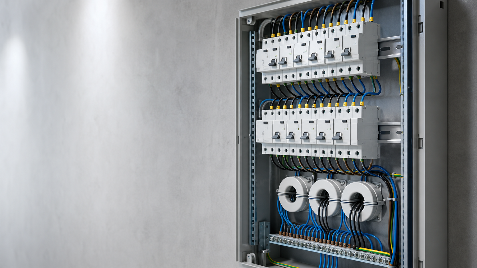
What an RCCB does and does not do
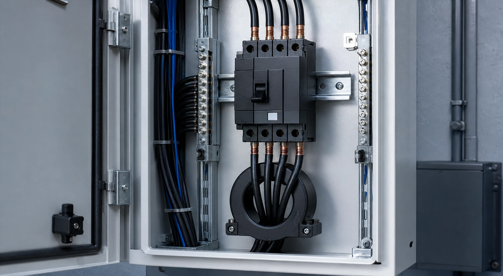
A residual current circuit breaker compares current flowing out on the line conductors with current returning on the neutral. In a healthy circuit these balance. If current is escaping to earth — through a person, damaged insulation or a wet enclosure — the balance is lost and the device opens at its rated residual operating current.
What it protects against:
What it does not do. A plain RCCB has no overload and no short-circuit protection and must sit in series with a suitably rated overcurrent device. It cannot detect a line-to-neutral fault, nor a series arc where current is unchanged but heat builds at a loose connection.
Where both functions are needed in one device, the correct product is an RCBO to IEC 61009-1.
- Direct and indirect contact with live parts, at 30 mA sensitivity.
- Earth leakage that would otherwise persist undetected and start a fire, at 100 to 300 mA.
- Insulation deterioration in cables and equipment, long before it becomes a short circuit.
Step 1: match the RCCB type to the load
This decision is most often made by habit rather than analysis, and getting it wrong means the device may fail to detect the fault it was installed to catch.
Table 1 — RCCB types and the residual current waveforms they detect
The practical rule. Any load with a rectifier input can produce a residual current that is not a clean sine wave, and a Type AC device may not respond at all. Since almost everything now contains a switched-mode supply, Type A is the sensible default and Type AC is a legacy specification.
Where Type B is mandatory in practice. EV charging points and PV inverters can inject smooth DC residual current, saturating the core of a Type A or F device and blinding it to further faults. Specify Type B, or verify the equipment includes integral 6 mA DC fault detection so an upstream Type A device remains valid.
Step 2: set the sensitivity IΔn
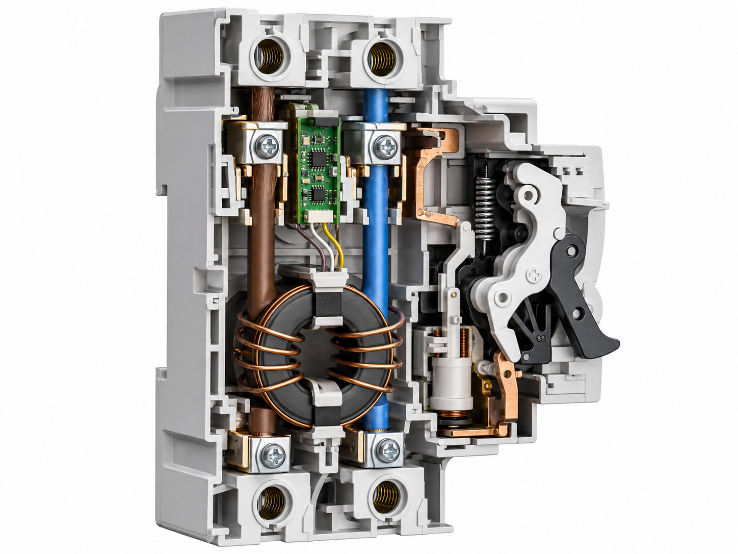
Rated residual operating current IΔn is where the device must operate. Equally important is the rated residual non-operating current IΔno, normally half of IΔn, below which it must not. WSB9LE-63 declares the pairing explicitly: 30 mA against 15 mA, 50 against 25, 100 against 50.
Discrimination between stages. For an upstream device to hold while a downstream device clears, the upstream IΔn should be at least three times the downstream value and must be time-delayed (Type S). Two instantaneous devices in series trip together regardless of rating. WJD36 is a Type S device with IΔn adjustable across 200-1000 mA and breaking time selectable at 0.5, 0.3 or 0.2 s — a natural upstream partner for 30 mA final circuits.
Standing leakage. A 30 mA device on a circuit already carrying 12 mA of filter and drive leakage has almost no margin. Measure it before deciding how many final circuits to group under one device.
- 30 mA — additional protection against electric shock. Socket-outlet circuits, portable equipment, bathrooms, kitchens, outdoor circuits and construction sites.
- 100 mA — intermediate. Used where 30 mA causes unacceptable nuisance tripping but shock protection still matters. Not a substitute for 30 mA on socket circuits.
- 300 mA — fire protection. Detects leakage associated with insulation breakdown that can ignite surrounding material. Typical for main incomers and sub-mains.
- 500 mA and above — equipment and cable protection. Larger boards and industrial feeders, where the objective is asset protection and discrimination.
Step 3: size the rated current In
The rated current of an RCCB is a thermal rating for its contacts, not a protective setting — the device will not open on overload. That gives a direct sizing rule.
In must be equal to or greater than the rated current of the overcurrent device protecting it. Fitting a 40 A RCCB behind a 63 A breaker leaves the contacts unprotected: a sustained 55 A load damages them without ever operating the upstream device.
Confirm the short-circuit withstand as well. WSB9LE-63 declares 6000 A or 10000 A at cos φ 0.7 depending on configuration, so check prospective fault current at the installation point against the selected variant.
NEUTRON DIN-rail devices run 6 to 63 A. For larger feeders the moulded case WCM30L covers 100, 225, 400 and 800 (630) A frames with Ui 660 V, Ue 380 V and Icu of 35 kA on the 100 A and 225 A frames, 50 kA on the 400 A and 800 A frames.
Step 4: poles and earthing arrangement
The RCCB must switch every live conductor, and in most arrangements that includes the neutral.
Earthing arrangements:
- 1P+N. Single-phase final circuits; both line and neutral pass through the sensing core and both are switched. WSB7L-63 is a 1P+N device.
- 2P. Single-phase, both poles switched, where a fully isolating device is required.
- 3P. Three-phase without neutral, for three-wire loads such as motors with no neutral connection.
- 3P+N and 4P. Three-phase with neutral. The neutral must pass through the sensing core, or the vector sum is meaningless and the device trips on normal unbalanced load. WSB7LE-63 and WSB9LE-63 both offer 1P+N, 2P, 3P, 3P+N and 4P.
- TT. High earth fault loop impedance through the mass of earth means overcurrent devices often cannot clear an earth fault in time, so residual current protection is effectively mandatory on every circuit.
- TN-S. A dedicated protective conductor gives low loop impedance, so overcurrent devices clear earth faults; RCCBs remain required as additional protection on socket and portable-equipment circuits.
- TN-C-S. Residual current protection cannot be applied upstream of the PEN separation point, because the PEN conductor carries both neutral and protective current and no imbalance is seen.
- IT. A first earth fault does not disconnect the supply and is signalled by an insulation monitoring device; residual current protection catches the second fault.
Voltage-independent versus electronic RCCBs
Two internal technologies exist and the distinction is a genuine safety consideration.
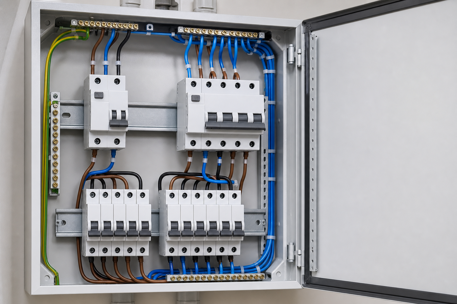
Voltage-independent (electromagnetic) devices use the residual current itself to drive a permanent-magnet tripping relay. No auxiliary supply is needed, so the device still operates if the neutral is lost or the supply collapses — the more robust architecture where supply quality is uncertain.
Voltage-dependent (electronic) devices use an amplifier powered from the monitored circuit, allowing adjustable sensitivity and delay, metering, communications and auto-reclosing — at the cost of depending on the supply.
NEUTRON builds both. The WCM7EL is an electronic residual current circuit breaker with adjustable overcurrent protection for three-phase four-wire TT systems; its LCD cycles through voltage, current and leakage. IΔn is selectable at 100, 200, 300, 500 or 800 mA (500 mA default), operating at 75 % ±5 % of setting with a 0.06 s delay.
It also offers auto-tracking: at startup it sets maximum sensitivity, then after ten minutes steps down to the range where measured leakage is below 50 % of the setting, locking out if tripping recurs at the highest range. Reclosing is configurable from 20 to 60 seconds — useful for remote distribution, but a deliberate design decision, since reclosing onto a genuine fault is not acceptable everywhere.
NEUTRON residual current range
Table 2 — NEUTRON residual current protection devices
Procurement checks and common mistakes
Ask every supplier for these:
Common mistakes. Specifying Type AC in an installation full of electronic loads. Fitting a 30 mA device across circuits whose standing leakage already approaches 15 mA. Sizing In below the upstream overcurrent device. Expecting discrimination from two instantaneous devices in series. Omitting the neutral from the sensing core on a three-phase circuit that carries neutral current. And treating the test button routine as optional.
Local qualification. National rules differ on where residual current protection is mandatory, on sensitivity and on test intervals. Confirm the destination market before finalising the schedule.
- Type test certification to IEC 61008-1 for RCCBs or IEC 61009-1 for RCBOs, from a recognised laboratory.
- Declared type (AC, A, F or B) marked on the device, not merely stated in the catalogue.
- Declared IΔn and IΔno, plus the time-delay classification where relevant.
- Declared short-circuit withstand or breaking capacity and the associated cos φ.
- Mechanical and electrical endurance figures.
- A test button on every device, with a documented test interval matching the destination market's installation rules.
This is general technical guidance. Confirm final ratings, protection coordination, standards, documentation and configuration against the approved project design and applicable local requirements.
Frequently asked questions
How do I choose the right RCCB type?
Start with the residual-current waveforms the connected load can produce, then confirm sensitivity, rated current, pole arrangement, earthing system and local requirements.
What is the difference between Type AC, A, F and B RCCBs?
The types define which residual-current waveforms the device can detect. The correct type follows the actual load and manufacturer guidance, not the circuit label alone.
Does an RCCB provide overload protection?
No. An RCCB provides residual-current protection and normally needs coordinated overcurrent protection from an MCB, MCCB or another approved device.
Bring the project inputs to the first review.
Specifying residual current protection for a distribution board or an export project? Send us the circuit schedule, earthing arrangement, load types and destination market and our engineers will return an RCCB and RCBO schedule with the correct type, sensitivity, rated current and pole configuration.
Request a quoteContinue learning
Explore related technical guidance in Electrical Protection.

Source article retained from the approved NEUTRON publishing file. Final ratings, standards, product documents and project configuration must be confirmed against the applicable requirements.