
What EN 50549 covers
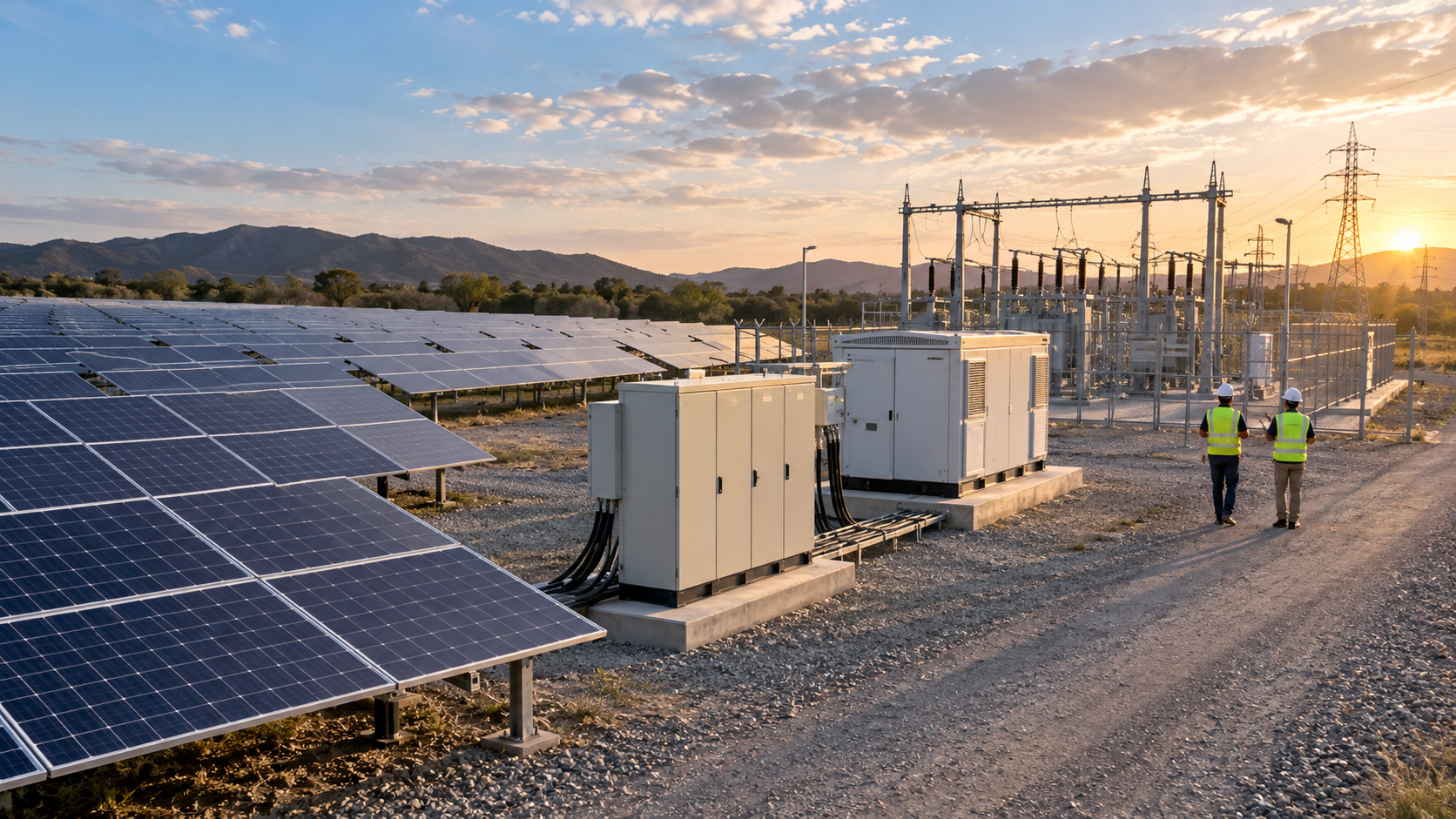
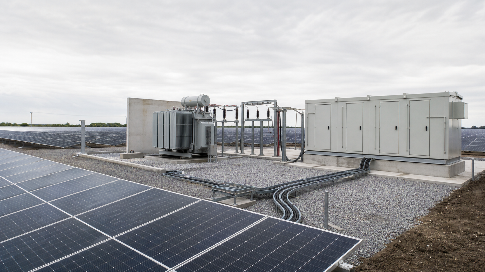
EN 50549 defines requirements for generating plants connected in parallel with public networks. EN 50549-1:2019 addresses low-voltage networks and EN 50549-2:2019 addresses medium-voltage networks. The documents cover interface protection, monitoring, and the behaviour expected of a generating plant at the point of common coupling. They are not a product standard for a single combiner box; they set system-level expectations that the plant owner and installer must satisfy through the plant design, protection scheme, and grid-operator agreement.
The combiner-box control boundary
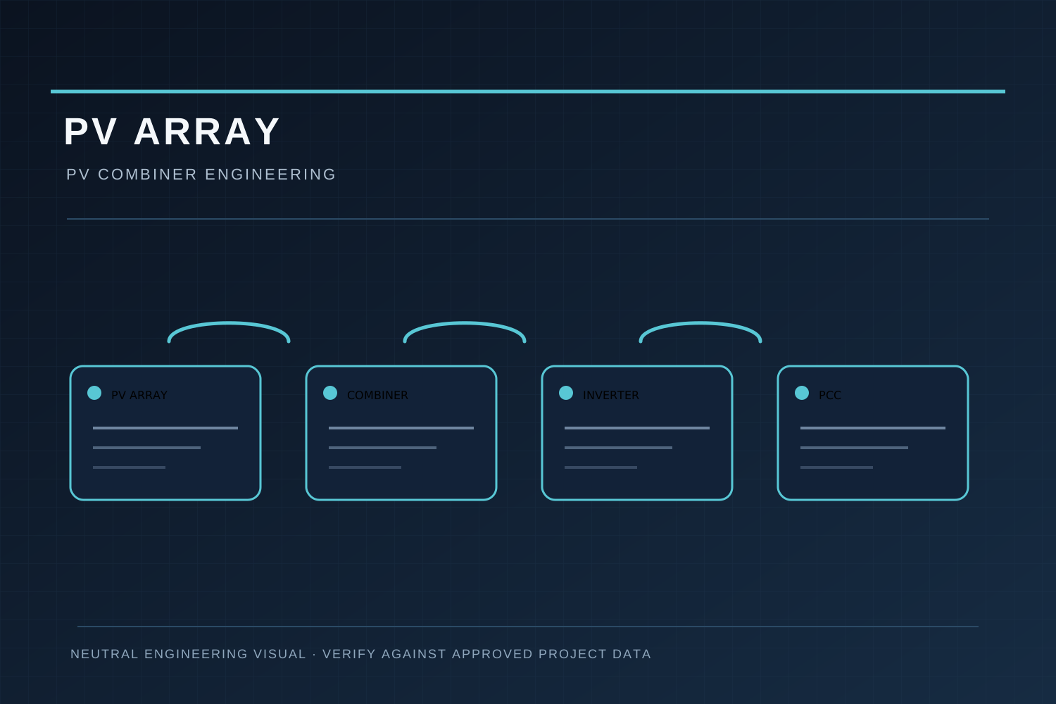
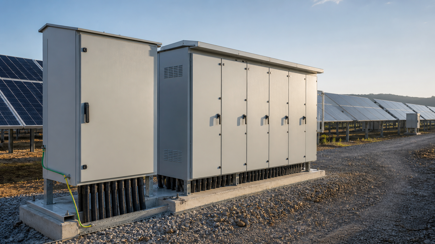
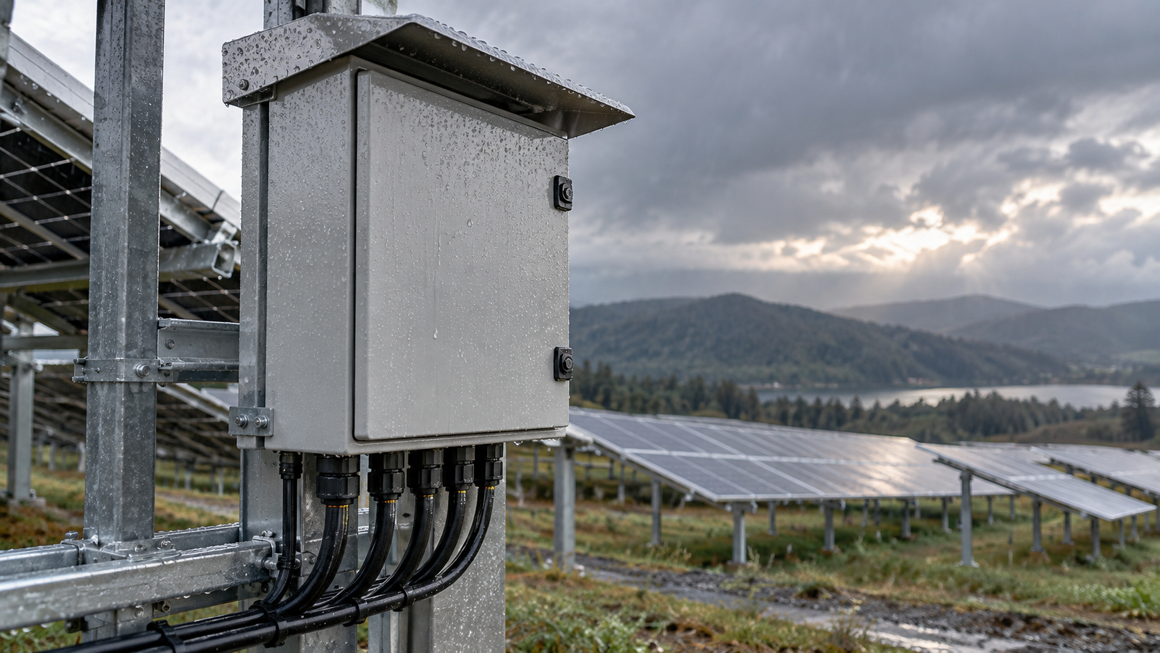
A combiner box aggregates PV input circuits into a DC output. Its disconnect or switching device forms part of the array-side isolation, not the full grid-connection control boundary. Grid-connection functions such as anti-islanding, reactive support, and trip-on-grid-loss reside in the inverter and the plant protection system at the network interface. A combiner box may carry a switch-disconnector for safe isolation and maintenance, but that device is not the element that performs grid-code protection. The boundary of responsibility must be drawn between the array, the combiner, the inverter, and the point of common coupling.
Opening the output does not de-energize the array
Opening or disconnecting the combiner-box output isolates the downstream DC bus from the inverter, but it does not remove energy from the PV input circuits or the internal busbar. Under daylight the PV modules continue to present an open-circuit voltage at their terminals and at the combiner input side. Only isolating every PV input circuit and verifying absence of voltage makes the inside safe to touch. Qualified personnel must follow a lock-out and tag-out procedure and confirm zero voltage before working. A switch-disconnector is an isolation device, not a fault-interrupting protector.
Local regulation and verification
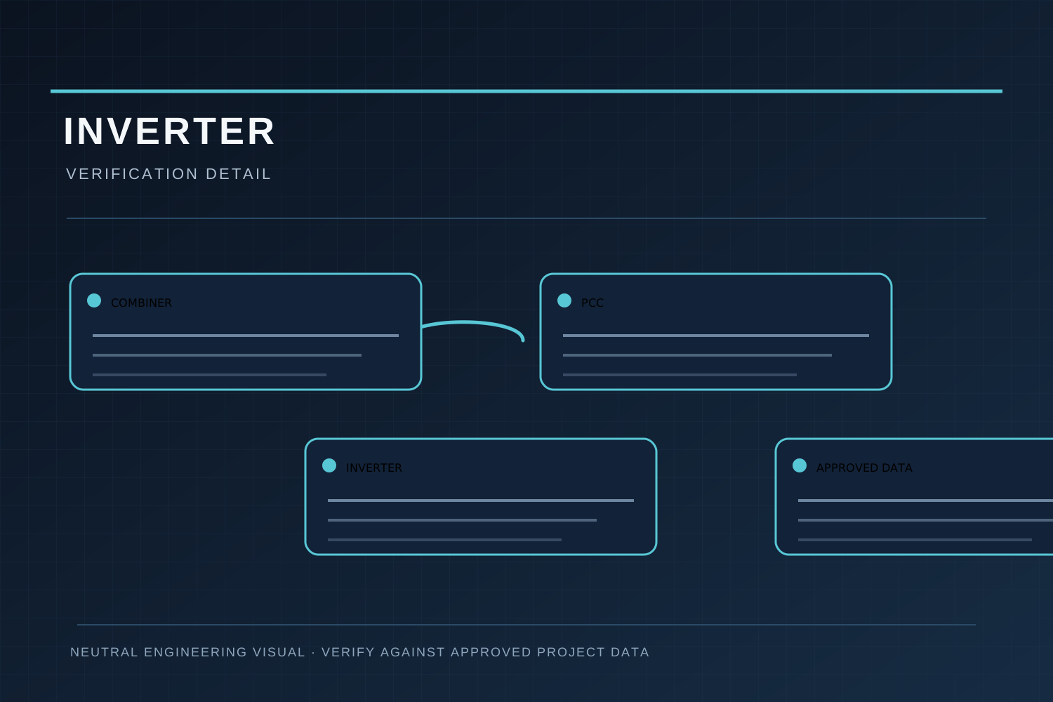
EN 50549 is transposed and supplemented by national and regional rules; the applicable clauses and any additional grid-operator requirements differ by location. Before installation, confirm the local regulation in force, the required interface protection settings, and the sign-off process with the distribution or transmission operator. Model-specific functions such as remote trip or monitoring must be verified against approved NEUTRON model datasheets and test reports. This article gives general orientation and is not a substitute for the applicable local regulation and the project engineering review.
This article preserves the accepted technical guidance but is not a substitute for the applicable local code, approved model datasheet, test report or a qualified engineer's design review.
Frequently asked questions
Does EN 50549 apply to a single combiner box?
No. It sets requirements for the generating plant at the network interface; a combiner box is one component within that plant, not the scope of the standard itself.
If I open the combiner output, is the array safe?
No. PV input circuits and the internal busbar can still be live under daylight. Isolate all inputs and verify zero voltage first.
Where does grid-code protection actually act?
At the inverter and plant protection system at the point of common coupling, not at the combiner-box output switch.
How do I know the local clauses?
Check the national transposition of EN 50549 and the grid operator connection rules; these vary by region and must be confirmed for the project.
Bring the project inputs to the first review.
Share the array layout, ratings, site conditions and documentation requirements for a coordinated review.
Discuss a projectContinue learning
Explore related technical guidance in Power Distribution.
Published from the accepted Period 13 manuscript (1.1); technical meaning and safety boundaries are retained from the approved source package.