

Bifacial Gain Is Site-Specific
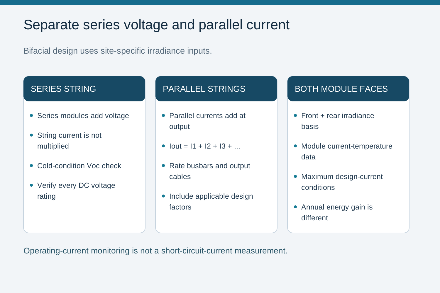
Bifacial modules collect irradiance on both faces. Rear-side contribution depends on albedo, mounting height, row geometry and shading, so the current basis for a combiner should reflect the actual array rather than a fixed percentage uplift.
Use module electrical data and the site design assumptions to determine maximum expected current. Annual energy-yield gain is not a substitute for the peak-current conditions used to rate conductors and protection.
Monitor Normalized Operating Current, Not Isc
Per-string monitoring measures operating current, not short-circuit current. Compare readings after accounting for effective front- and rear-side irradiance, module temperature and operating point. Isc is a separate test or model parameter and must not be inferred directly from a normal operating-current reading.
Account for effective irradiance on both module faces and the applicable temperature response.
Compare strings at equal conditions to detect mismatch early.
Set alarm thresholds for the site and sensor accuracy, excluding known shading and low-irradiance periods.
Fuse Uprating Needs a Verified Basis
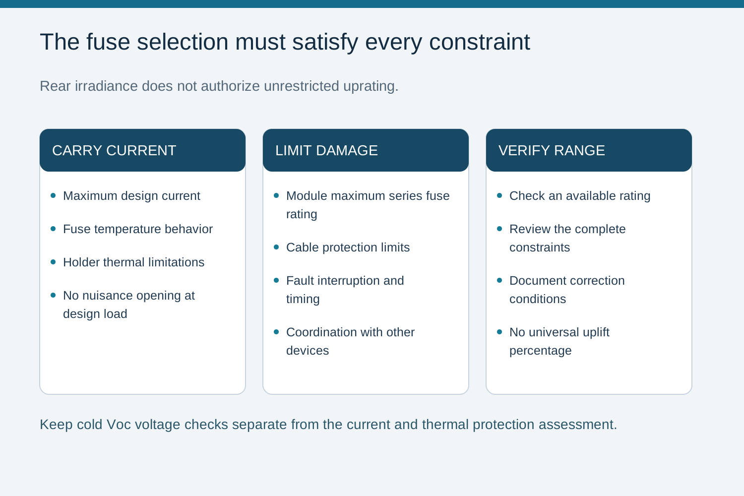
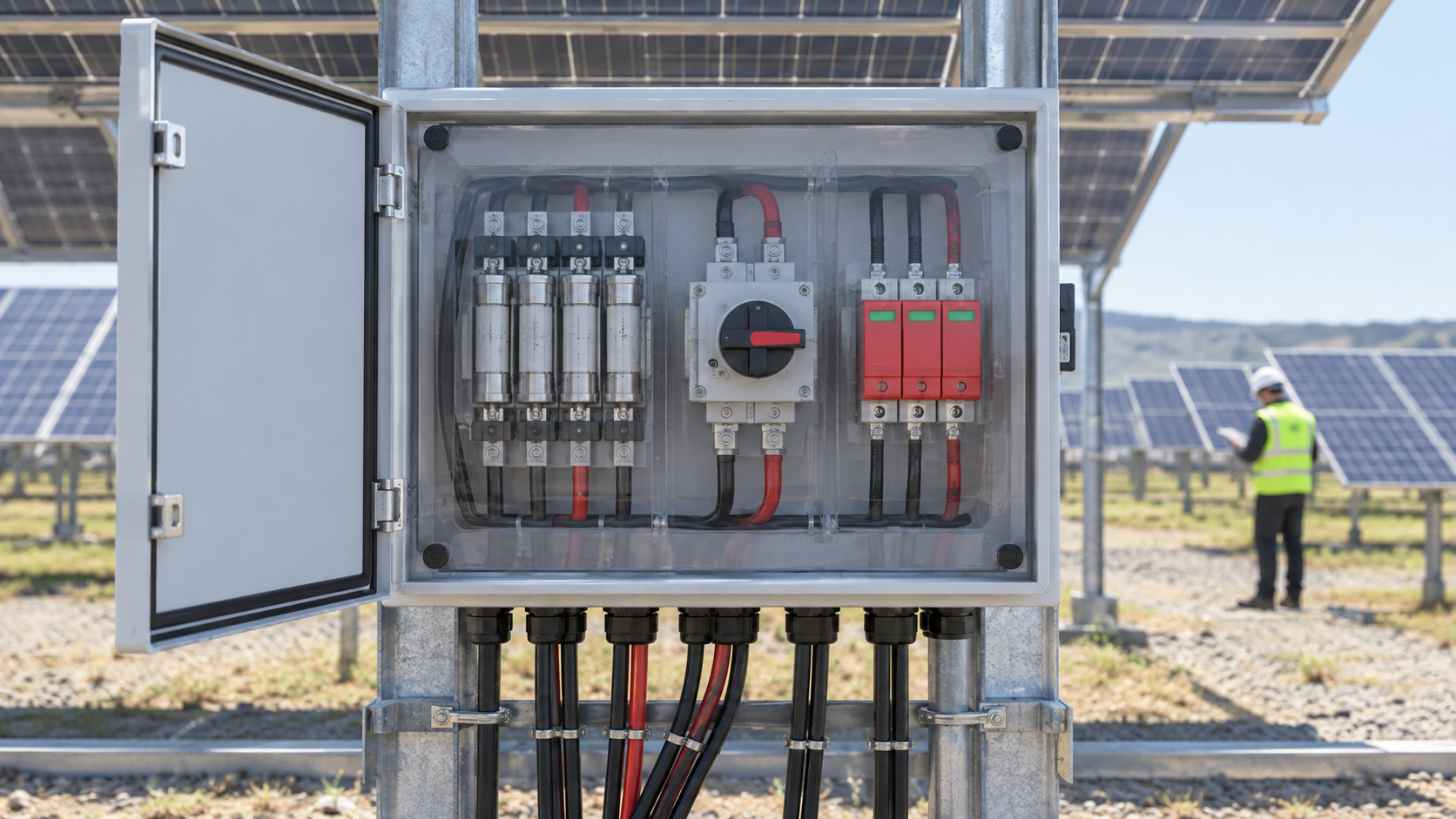
Select string protection, where required, using design current, the module maximum series fuse rating, cable limits and the fuse and holder temperature characteristics. A larger rear contribution does not permit an unlimited fuse increase. Check the acceptable rating range before selecting the next available fuse size.
Check the module-marked maximum series fuse rating.
Check fuse and holder current limits and their specified temperature correction.
Confirm fault-current interruption and coordination with the other protective devices.
1500 V and Current Reality
Voltage class and current aggregation are separate checks. A higher permitted voltage can allow more modules in series, but series-connected modules do not add their currents. Each string current follows its module characteristics and conditions; parallel string currents add at the combiner output. Check maximum voltage using cold-condition Voc and maximum design current using the applicable irradiance and current-temperature assumptions.
Calculate the maximum expected effective Isc using module data, both-face irradiance, the current temperature coefficient and the factors required by the design method.
Check cold-condition string Voc separately against every connected DC component rating.
Keep the per-string current calculation separate from the sum used for busbars and output conductors.
Configuration Enquiry with NEUTRON
For a bifacial-array configuration enquiry, provide NEUTRON LLC with module data, the rear-irradiance current assumptions, series module count, parallel string count, maximum voltage and the single-line diagram. State any requested monitoring function separately from the electrical current ratings.
Confirm the applicable installation rules, current manufacturer instructions and exact assembly configuration with a qualified design engineer.
Frequently asked questions
Should I monitor Isc per string?
Monitor operating current and interpret it using effective front- and rear-side irradiance, temperature and operating conditions. Isc is a separate short-circuit parameter, not the normal string working current.
Does bifacial automatically allow bigger fuses?
No. The selected fuse must remain within module and cable protection limits while carrying design current under the fuse and holder temperature conditions. Use peak-current assumptions, not annual yield gain, for this check.
Does 1500 V lower string current?
Not by itself. String current depends on the modules and operating conditions. Modules added in series mainly add voltage; parallel strings add current at the combiner output.
How do I size bifacial protection?
Determine maximum current from module data, effective irradiance on both faces, current-temperature response and applicable design factors. Check cold Voc separately for voltage, then coordinate fuses, cables and holders within their limits.
Bring the design basis to the configuration review.
Provide the module and inverter data, string topology, site conditions and required verification documents.
Discuss a projectContinue learning
Explore related technical guidance in Solar PV.
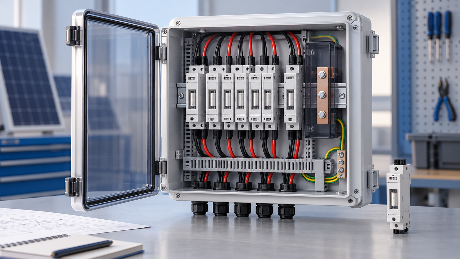
Technical guidance: confirm the exact model, applicable standard edition and project-specific conditions. Illustrations explain engineering decisions and do not certify a product.