
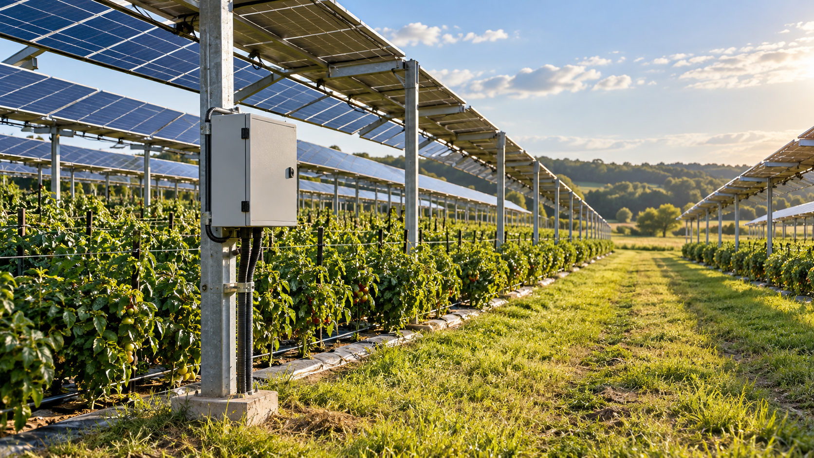
Map farm operations around the array
Agrivoltaic sites combine electrical infrastructure with crop work, grazing, irrigation and machinery movement. A combiner location that works on an empty plan may block a tractor route, sit in a spray path or become inaccessible during planting and harvest. Map operating lanes, crop rows, livestock boundaries, water sources and seasonal work areas.
The PV system still needs a documented DC circuit schedule, protection design and safe service boundary. IEC 62548-1 provides PV array design requirements that include DC wiring, protection, switching and earthing; the agricultural layout adds site constraints that the electrical designer must coordinate.
- Mark machinery envelopes and seasonal routes.
- Identify crop, livestock and irrigation activity near equipment.
- Agree who controls access and isolation during farm operations.
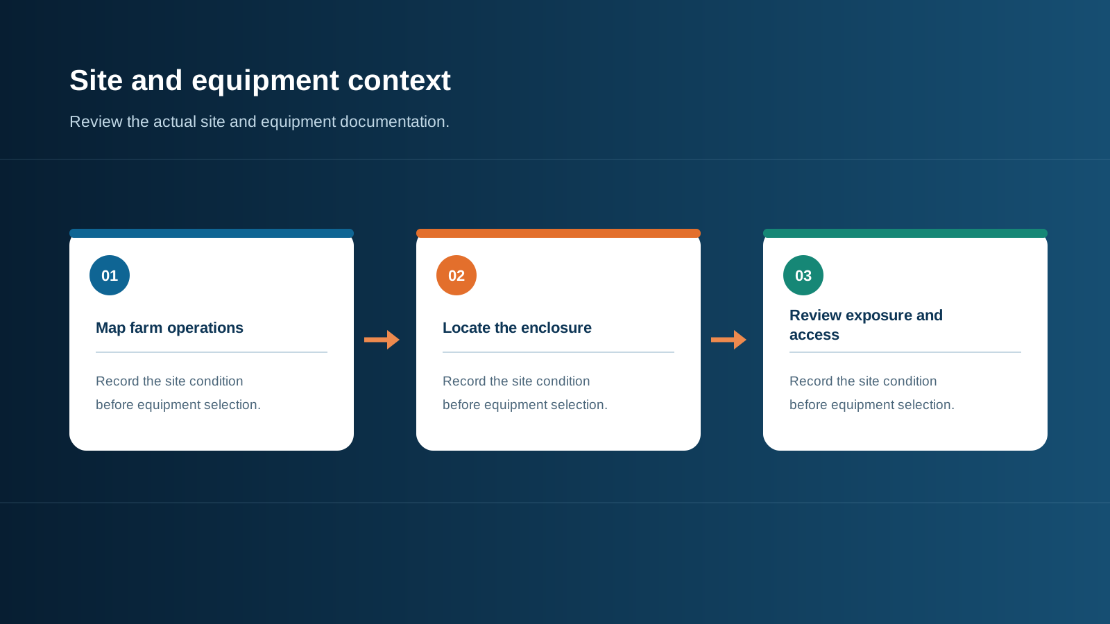
Technical diagram shown at a readable responsive scale.
Choose a location for safe service
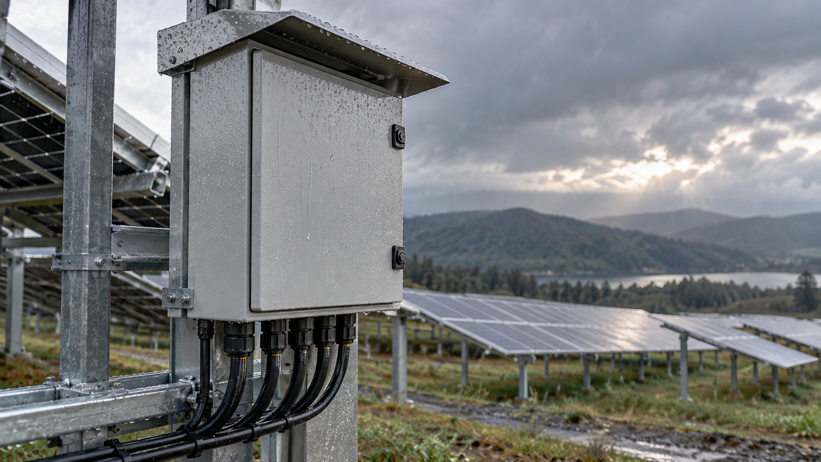
Place the enclosure where qualified staff can reach it without entering an unsafe vehicle path or damaging crops. Check door clearance, working space, mounting support and the route for carrying test equipment. A post or raised mount may help in some layouts, but height and support must fit the actual site and access method.
Review future crop height, pruning, harvesting equipment and vegetation growth. Keep labels visible and avoid relying on a service route that disappears when the field is wet or planted.
- Confirm year-round access, not only the commissioning route.
- Keep equipment outside machinery impact and irrigation spray zones where practical.
- Include the access path in the farm operating plan.
Specify enclosure and materials from exposure
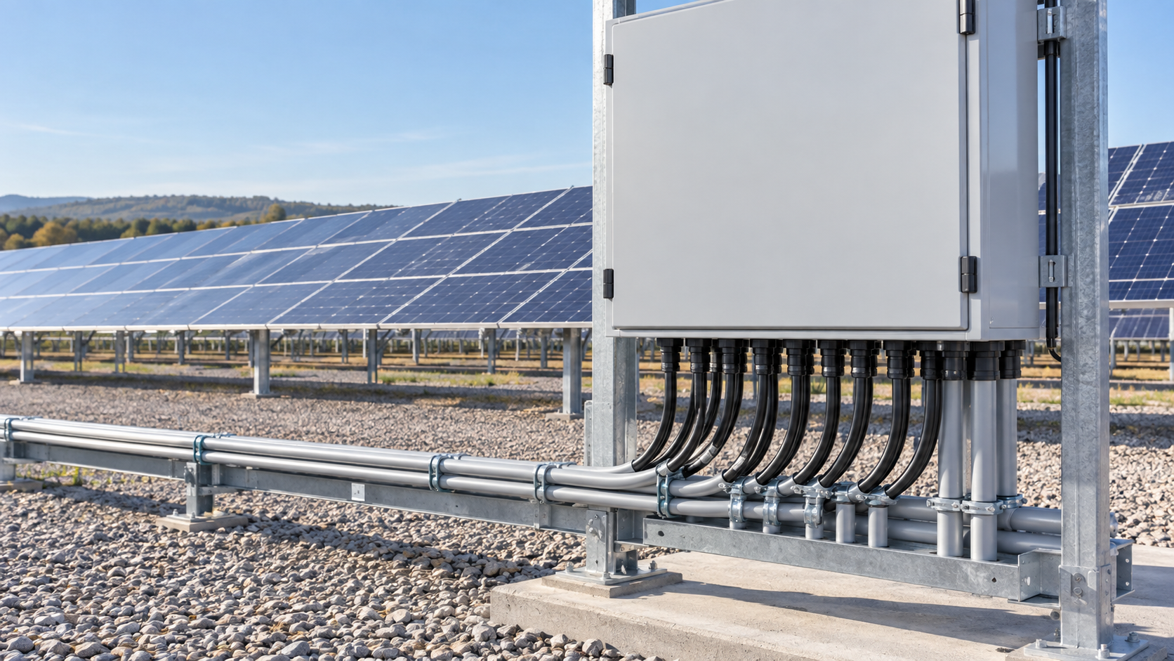
Dust, rain, washdown, fertilizer, manure and irrigation water vary by crop, process and local climate. Describe each exposure and use that information to set enclosure protection and materials. IEC 60529 provides the IP classification framework, but it does not establish chemical compatibility or prove that a field-modified enclosure keeps its marked rating.
Check doors, seals, glands, fasteners, support brackets, coatings and labels. If filters or vents are used, include their rating and service interval. Material selection should be supported by documentation for the actual chemical and weather exposure rather than a generic rural-site assumption.
- List cleaning agents, fertilizers and nearby chemicals.
- Check the rating of every penetration and accessory.
- Document inspection or filter replacement intervals.
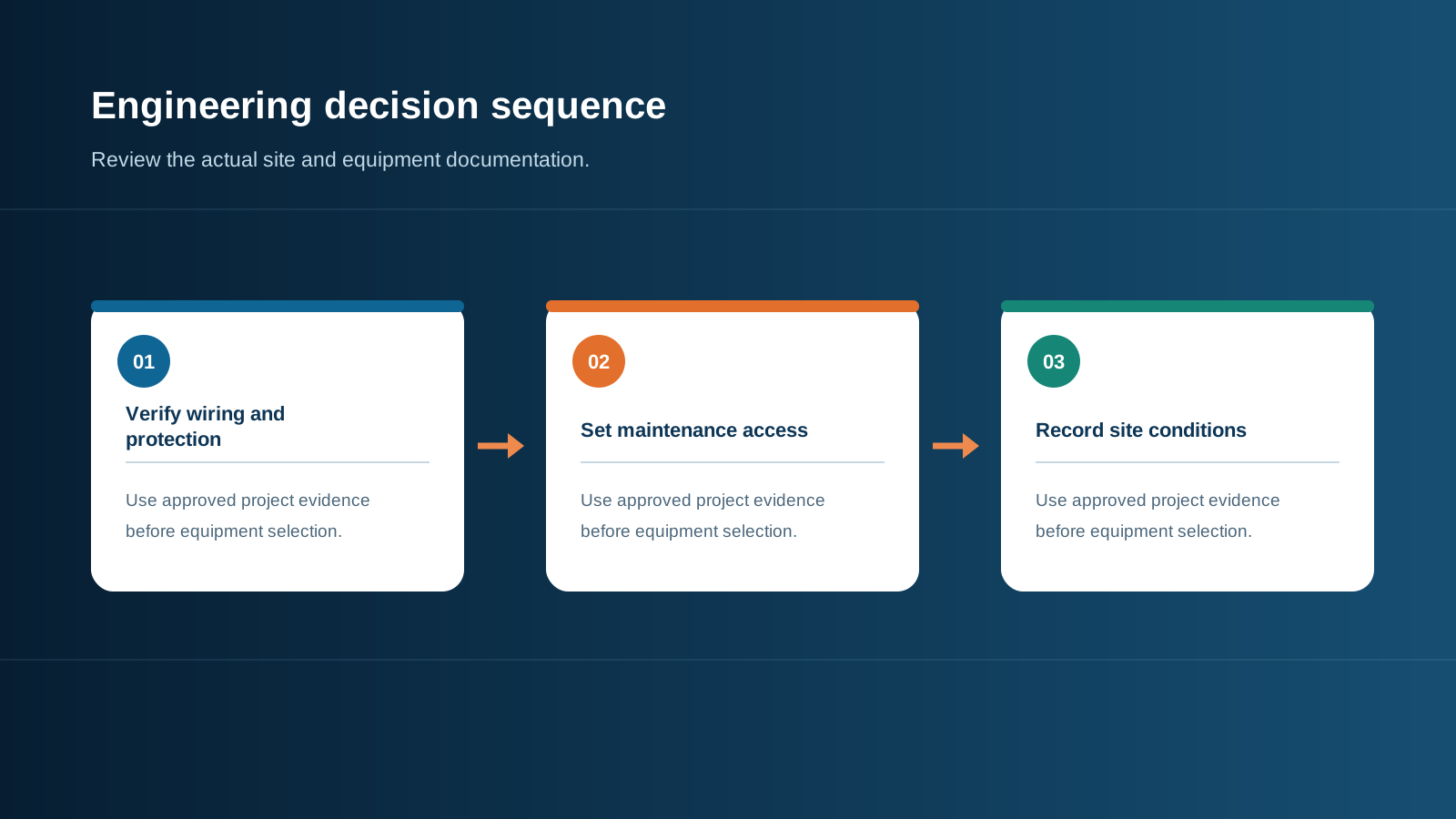
Technical diagram shown at a readable responsive scale.
Protect cables from machinery and water
Route conductors away from turning equipment, animal contact, standing water and repeated impact. Use the cable type, support spacing and mechanical protection required by the approved electrical design and local rules. Confirm conduit crossings and transitions do not conflict with farm roads, gates or irrigation maintenance.
Keep circuit identification visible at the enclosure and relevant field interfaces. Where a route crosses a work area, coordinate it with electrical drawings and the farm operating map so repairs do not require guesswork.
- Mark crossings and protect exposed routes as designed.
- Check entry fittings and strain relief after seasonal ground movement.
- Avoid routes that create trip, snag or machinery hazards.
Coordinate voltage, protection and monitoring
Derive system voltage and string current from module data and the project design. Select fuses, switchgear, conductors and surge protective devices to match those inputs and actual fault conditions. Do not infer a 1 000 V or 1 500 V class from the agrivoltaics label or project size.
Remote monitoring may help when technical staff are far away, but specify the measured point, data quality, alarm behavior, communication path and local response. An enclosure alarm or current comparison is an indication for investigation, not proof of a particular fault.
- State design maximum voltage and string arrangement.
- Confirm device and interface ratings from exact model documentation.
- Define lost-data, alarm-acknowledgement and field-follow-up behavior.
Technical diagram shown at a readable responsive scale.
Plan maintenance around the crop calendar
Schedule inspection access around planting, spraying, harvest and livestock movement. The interval should follow equipment manuals, site exposure and the approved maintenance plan. Inspect the enclosure and supports for damage, seal condition, corrosion, pests, cable wear, labels and signs of water or dust entry.
Record checks and corrective work with circuit location and date. Compare installed components with the approved schedule before replacement; a similar-looking substitute can have a different voltage, temperature or enclosure rating.
- Agree access windows with the farm operator.
- Retain inspection, cleaning and replacement records.
- Update drawings when a route or enclosure is moved.
General engineering information, not a project design, product certificate, code determination or safe-work procedure. Verify final ratings, installation, protection coordination and local requirements against current standards, exact manufacturer documentation and the approved project design.
Frequently asked questions
Is IP65 suitable for every agrivoltaic site?
No universal IP rating applies. Base the requirement on dust, water, washdown and installation details, then verify the complete enclosure and entries against current documentation.
Should a combiner box always be pole-mounted on a farm?
No. Select mounting height and support from machinery clearance, service access, crop layout, structural conditions and local installation rules.
How should fertilizer or irrigation exposure affect material choice?
Describe the actual chemicals and exposure pattern, then check coatings, seals, fasteners and enclosure materials against supplier compatibility data.
How do you protect combiner cables from farm machinery?
Coordinate cable routes with machinery paths and irrigation, and use mechanical protection and support specified in the approved electrical design.
What should remote monitoring report?
Define measured points, signal ratings, data freshness, communication-failure state and operator response. An alarm is an investigation trigger, not a confirmed diagnosis.
Review the project inputs
Share the system voltage, circuit schedule, installation location and site conditions so the equipment discussion can be checked against approved project documentation.
Discuss a projectContinue learning
Explore related technical guidance in Solar PV.

Prepared from the approved Period 09 source package with technical claims revised to retain project-specific and manufacturer-specific limits. Official source pages describe scope; they do not certify a NEUTRON product configuration or a customer installation.