

How bifacial panels generate
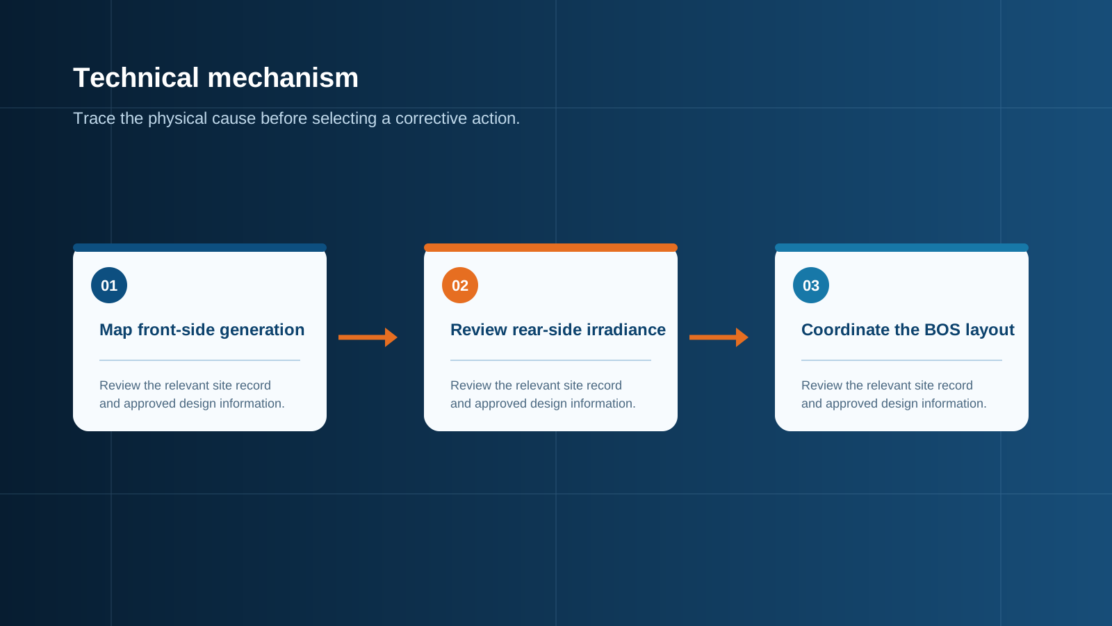
A bifacial cell is passivated and metallised so that light entering from the rear can also generate carriers. The module is built to let that light through: instead of an opaque polymer backsheet, it uses a glass rear cover or a transparent backsheet, and the rear metallisation is a grid rather than a full sheet. The result is a module with a front-side rating measured under standard conditions and a separate rear-side response, expressed as a bifaciality factor.
Bifaciality factor is the ratio of rear-side efficiency to front-side efficiency, typically 0.65 to 0.85 for current products. It is a property of the cell, not a promise of extra energy. The actual gain depends entirely on how much light reaches the rear face, which is a function of the installation rather than the module.
Technical diagram shown at a readable responsive scale.
Rear-side gain and albedo
Albedo is the fraction of incident light a surface reflects. It is the dominant variable in rear-side gain, and it varies enormously between site surfaces. Fresh snow reflects most of the light that hits it, light concrete and white membrane roofs reflect a substantial share, dry sand and gravel are moderate, and dark asphalt or green vegetation reflect very little.
Realistic annual gains run from a few percent on dark vegetated ground to around twenty percent or more on highly reflective surfaces with elevated racking. Any energy model that assumes a fixed gain without specifying the ground surface should be treated with caution.
- Snow cover: very high reflectance, producing the largest seasonal rear gains.
- White membrane roofing, light concrete or crushed white stone: high reflectance, commonly engineered deliberately.
- Sand, gravel and dry soil: moderate reflectance and a reliable baseline in arid sites.
- Grass, dark soil and asphalt: low reflectance, where bifacial gain is marginal and hard to justify.
Mounting height and ground reflectance
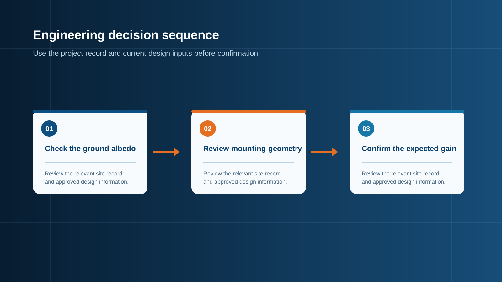
Rear-side irradiance is not uniform. The module shades the ground directly beneath it, so the light reaching the rear face comes largely from the surrounding illuminated area. Raising the module increases the view of that illuminated surface and evens out the rear irradiance distribution, which is why elevation matters almost as much as albedo.
Gain rises quickly as clearance increases from a few centimetres to around one metre, then flattens. Wider row spacing helps for the same reason, since a tighter pitch means neighbouring rows shade more of the reflective ground. This is also why flush-mounted rooftop bifacial installations capture very little rear gain: with almost no gap behind the module and a shaded surface below it, the rear face has nothing to collect. Bifacial modules belong on elevated racking, on reflective flat roofs with a standoff, or on trackers — not lying against a roof surface.
Technical diagram shown at a readable responsive scale.
Why shading only matters on the front
Front-side shading behaves exactly as it does in a monofacial array: a shadow across cells forces the affected substring towards reverse bias, its bypass diode conducts, and the string current falls to the level the shaded module can pass. Bifaciality does not rescue a front-shaded module, because the rear contribution is a fraction of the front and cannot make up a hard shadow.
Rear-side obstruction is a different matter. Racking rails, cable trays, junction boxes and mounting clamps block part of the rear view, and this reduces gain smoothly and proportionally rather than triggering diode action. There is no hot-spot mechanism and no step change in output. The practical implication is that rear-side clutter should be minimised for yield, while front-side shading remains the safety-relevant concern that drives layout and string grouping decisions.
Bifacial effect on string current
This is the point where bifacial design meets electrical design. Rear irradiance adds to front irradiance at the cell, so both operating current and short-circuit current rise above the front-side datasheet figures. A module with a front-side short-circuit current of 14 amperes and a realised rear gain of ten percent will present approximately 15.4 amperes to the string under those conditions, and more during a brief high-irradiance event when a bright cloud edge lifts total irradiance above the standard test level.
Voltage is barely affected — open-circuit voltage moves only logarithmically with irradiance — so string length rules are essentially unchanged. Current, however, scales almost linearly, and current is what determines fuse rating, conductor cross-section, busbar cross-section and terminal rating. Treating a bifacial array as though it were monofacial therefore under-rates precisely the components that carry the extra energy.
- Short-circuit current rises roughly in proportion to total irradiance including the rear contribution.
- Open-circuit voltage is essentially unchanged, so maximum series count per string is set by temperature as usual.
- Design against the peak realised current at the site, not the annual average gain.
Fuse and busbar sizing for peak current
The established practice for string overcurrent protection is a photovoltaic-rated fuse sized at no less than 1.25 times the string short-circuit current. For a bifacial array, the short-circuit current used in that calculation must be the value including realised rear gain, not the front-side nameplate. Continuing the earlier example: 14 amperes front-side plus ten percent rear gain gives 15.4 amperes; multiplying by 1.25 gives 19.25 amperes, so a 20-ampere photovoltaic fuse is the minimum defensible choice, not the 16-ampere class that a front-only calculation would suggest.
The same correction applies to every current-carrying element in the chain. Conductor cross-section into the enclosure must carry the corrected current with acceptable temperature rise, the output busbar must be rated for the sum of all corrected string currents at the site's high-temperature condition, and terminal blocks and fuse holders must be rated for their share with margin for thermal cycling.
Undersized string protection is the single most common defect in bifacial arrays, and it announces itself as nuisance fuse operation on the brightest, most productive days of the year — exactly when the lost production is most expensive.
- Apply the 1.25 factor to the gain-corrected short-circuit current, then round up to the next standard fuse rating.
- Use fuses and holders designed for photovoltaic direct-current duty at the full system voltage — general-purpose devices are not equivalent.
- Rate the busbar and terminations for the summed corrected current, with derating for enclosure internal temperature.
- Confirm the direct-current isolation device and surge protective device ratings match the array's maximum system voltage.
Layout and tracker considerations
Layout choices that raise rear gain are elevation, wider row pitch, a reflective and well-maintained ground surface, and clean rear glass. Single-axis trackers combine naturally with bifacial modules because the elevated torque tube already provides clearance and the tracking motion keeps the front face productive while the rear collects reflected light through the day.
The design tension is economic: wider pitch and greater elevation increase gain but consume land and steel. Because the extra energy appears as extra current, every increment of gain that the layout captures must be carried through the wiring and the combining stage. Locking the layout before the electrical equipment is specified avoids the awkward situation of a re-optimised field arriving with under-rated protection.
Matching BOS to bifacial strings
Specifying the combining and protection stage for a bifacial array needs four numbers: the maximum system direct-current voltage, the gain-corrected string short-circuit current, the number of input strings, and the site environmental class including expected internal enclosure temperature. With those, string fuse rating, busbar cross-section, isolation device rating and surge protection selection all follow deterministically.
Because rear gain varies with season, soiling and ground condition, the correct design basis is the peak expected condition rather than the average. Per-string current measurement at the combining point is also worth more on bifacial plants than on conventional ones, since it is the only practical way to confirm that the modelled gain is actually being realised and that no string is operating near its protective limit. NEUTRON reviews module bifaciality, layout and site data and prepares a configuration discussion for the combining, protection and busbar equipment sized to the array's real peak current.
This is general technical guidance. Confirm final ratings, protection coordination, installation and applicable local requirements against current standards, manufacturer documentation and the approved project design.
Frequently asked questions
How much extra energy from bifacial?
Realistic annual gains run from a few percent to around twenty percent or more. The module's bifaciality factor, typically 0.65 to 0.85, sets the ceiling, but the actual result is decided by the installation rather than the module.
What raises rear gain?
Four factors dominate. High ground reflectance is the strongest: white membrane, light concrete, crushed white stone, dry sand or snow cover all deliver far more rear irradiance than grass or dark asphalt.
Discuss your PV requirement
Share the system voltage, string arrangement, inverter interface and installation environment. NEUTRON can review the equipment configuration around your project documentation.
Discuss a projectContinue learning
Explore related technical guidance in Solar PV.


Published from the approved Period 06 source package. Technical values and final design decisions must be verified against the current applicable standard, manufacturer documentation and approved project design.