
The Quick Answer
The distinction is energy class and installation location, not brand or price.
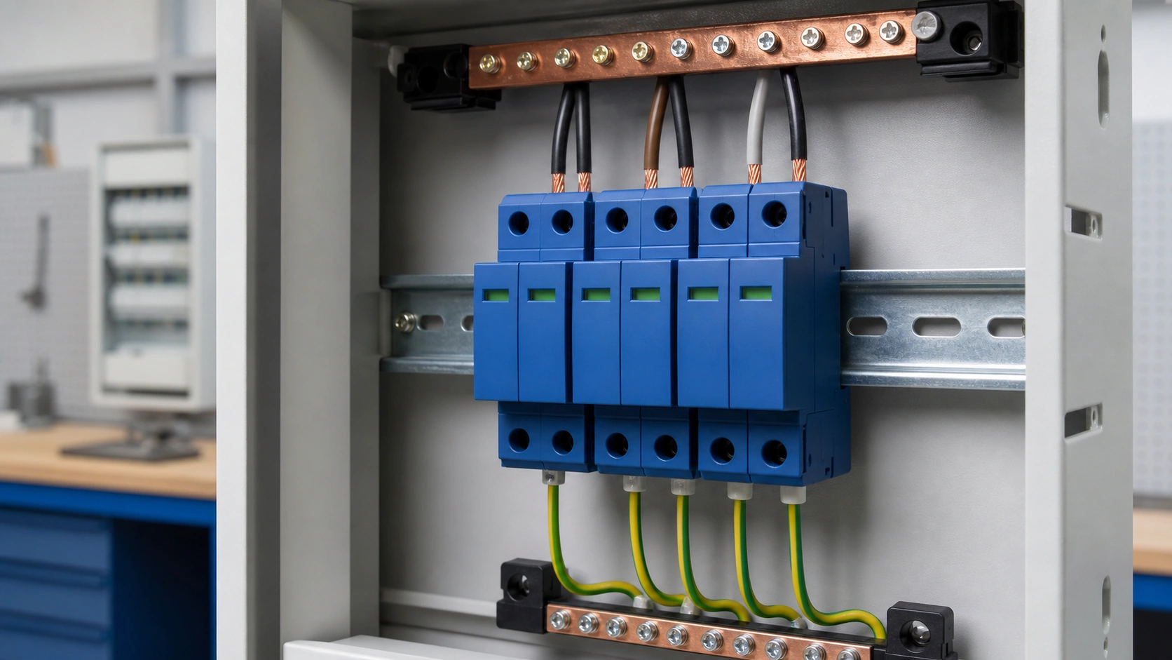
- Type 1 lightning arrester: partial lightning current on a 10/350 µs waveform, rated by Iimp.
- Type 2 surge protective device: induced and switching surges on an 8/20 µs waveform, rated by In and Imax.
- Type 3 fine protection: close to sensitive equipment and rated using a combination wave.
How a Lightning Arrester Works
A lightning arrester provides a deliberate low-impedance path to earth for current that might otherwise flash over the installation's insulation. Spark gaps and gas-discharge tubes switch into conduction; medium- and high-voltage metal-oxide arresters use zinc-oxide blocks with a strongly nonlinear characteristic.
Key ratings include MCOV or Uc, impulse discharge current Iimp on the 10/350 µs waveform, and Up, the residual voltage across the protected circuit.
How a Low-Voltage Surge Protective Device Works
A Type 2 SPD is commonly built around metal-oxide varistors. Below the varistor voltage it draws only a small leakage current; above it, resistance falls rapidly and the device shunts surge current away from the load while clamping the voltage. When the transient passes, it returns to a high-resistance state.
Because an MOV clamps rather than crowbars, the protection behavior and follow-current considerations differ from a spark-gap arrester.
Iimp Versus In: The Parameter That Decides Everything
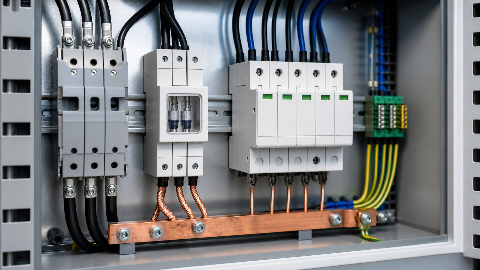
Do not compare kA figures without checking the waveform. Iimp on 10/350 µs represents a direct lightning-current impulse with high charge and specific energy. In and Imax on 8/20 µs represent shorter induced and switching surges.
A 40 kA Type 2 device on an 8/20 µs test is therefore not a substitute for a 12.5 kA Type 1 device on a 10/350 µs test. Up is equally important because it describes the residual voltage that the protected equipment sees.
Cascaded Type 1, Type 2 and Type 3 Coordination
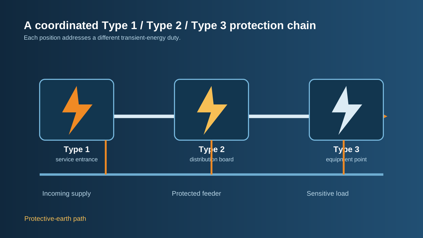
Energy coordination means that each stage handles the part of the event it is designed for and passes a reduced residue to the next stage. Use manufacturer coordination tables when devices come from different ranges.
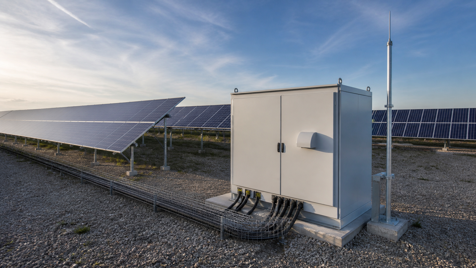
Cable inductance between stages provides decoupling. A separation of at least 10 m between Type 1 and Type 2 is a common design rule; when the physical distance is shorter, use a decoupling inductor or a tested combined device. A typical 230/400 V TN-S architecture places Type 1 at the main board, Type 2 at sub-distribution and PV combiner locations, and Type 3 close to sensitive equipment.
Technical diagram shown at a readable responsive scale.
Modular SPD Configuration in the Source Brief
The source brief describes a modular WCU8 surge-protective-device range for AC 50/60 Hz distribution systems at 230 V and 440 V, with plug-in cartridges, thermal disconnection, status indication, remote signalling and configurations for TT, TN-S and TN-C systems. Confirm all ratings and code details against the exact quotation and applicable standard.
Installation Rules That Decide Whether Protection Works
An SPD with good ratings can still fail to protect equipment if it is wired badly. Lead length matters because inductive voltage drop adds to the let-through voltage during a fast transient.
- Keep the total connecting and earthing conductor length as short as practical; the source brief specifies 50 cm or less.
- Use a V-shaped or Kelvin connection so surge current does not share the protected load path.
- Keep the earthing conductor short, straight and free of tight bends.
- Provide coordinated backup overcurrent protection.
- Bond incoming power, data, telecoms and metallic services to the same equipotential system where required.
Selection Checklist and Common Mistakes
Start with an IEC 62305 risk assessment and confirm the earthing arrangement before selecting the module configuration.
- Select Type 1 where the risk assessment requires it.
- Select Uc above the maximum expected operating and temporary-overvoltage condition.
- Check Up against equipment impulse withstand, including lead-length voltage.
- Specify remote signalling where the board is not regularly visited.
- Record installation date and monitor end-of-life status indicators.
- Do not compare 8/20 µs kA directly with 10/350 µs kA.
Surge protection reduces risk but does not eliminate it. Risk assessment, earthing, equipotential bonding and destination-market wiring rules remain controlling requirements.
Frequently asked questions
Is a lightning arrester the same as a surge protector?
No. A Type 1 lightning arrester diverts partial lightning current tested on 10/350 µs at the service entrance. A typical Type 2 SPD clamps induced and switching transients tested on 8/20 µs at distribution boards. They normally work together.
Can a Type 2 SPD replace a Type 1 arrester?
Not where an IEC 62305 risk assessment calls for Type 1. The 8/20 µs test carries much less charge and specific energy than a comparable 10/350 µs test.
What is the difference between MOV and GDT technology?
An MOV clamps by sharply reducing resistance above its varistor voltage. A GDT switches by ionising and collapsing to a low arc voltage, so it handles a different energy and follow-current problem.
How long does an SPD last?
There is no fixed lifetime. Surge exposure and grid conditions age MOV modules cumulatively. A thermal disconnector, status window and optional remote contact help identify end of life.
How close must an SPD be to the equipment it protects?
Conductor length is critical. Keep connecting and earthing conductors short, with the source brief specifying a total of 50 cm or less where practical, and use a V-shaped connection.
Coordinate the Protection Chain
Share the single-line diagram, earthing arrangement, ratings and destination-market standard so the Type 1/2/3 arrangement and wiring scope can be reviewed together.
Request a quoteContinue learning
Explore related technical guidance in Electrical Protection.


Converted from NEUTRON_PUBLISH_lightning-arrester-vs-surge-protector_v1.0.docx. Waveform, coordination and installation guidance is retained from the source.