
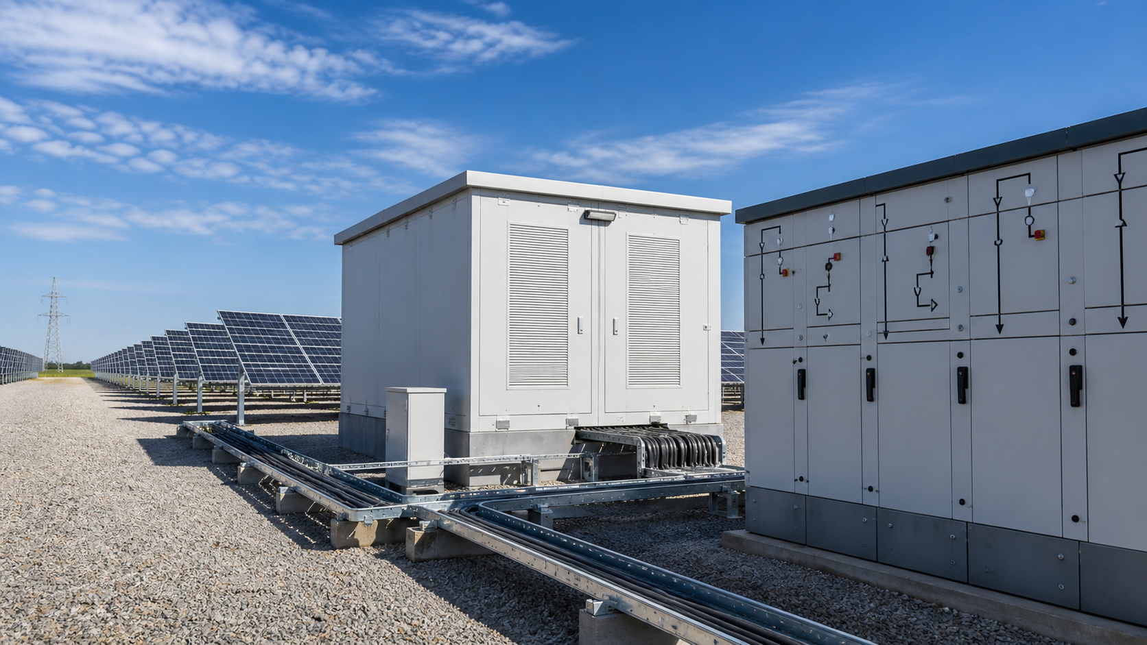
1. Distribution architecture of a large PV plant
A large PV plant distributes generated power through three electrical tiers:
Within the collector tier, string and central inverters feed compact substations. The medium-voltage feeds are routed through a ring or radial topology using ring main units, then aggregated at the plant step-up substation before the high-voltage transmission connection.
- The low-voltage (LV) side, where inverters output 400 V / 690 V AC after converting the DC strings.
- The medium-voltage (MV) collector network, where step-up transformers raise inverter output to 33 kV or 35 kV for transport across the site.
- The step-up substation, where a main power transformer raises the MV collector voltage to the grid voltage (110 kV, 220 kV, 400 kV and beyond).
2. Step-up substation function and transformer
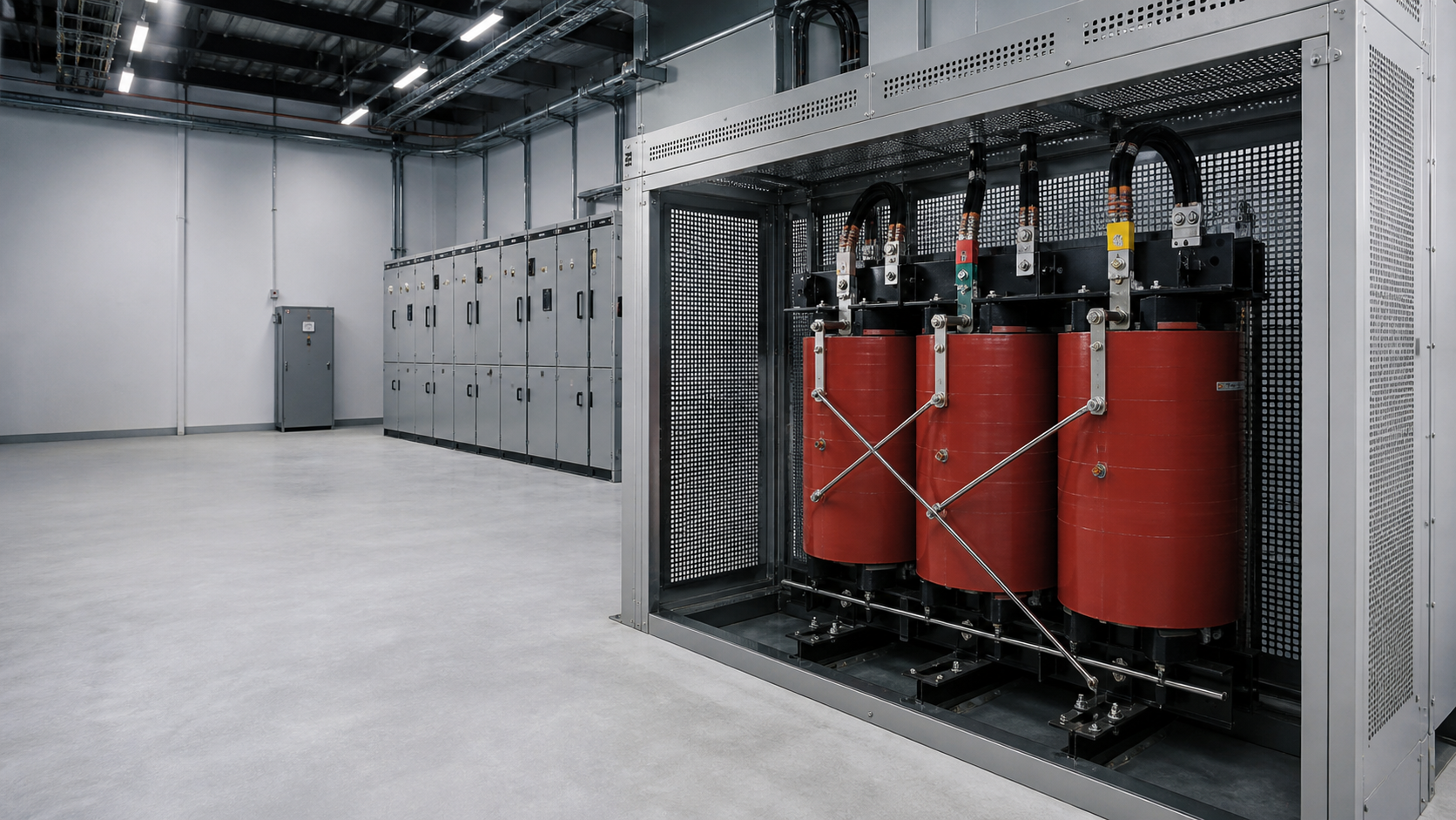
The step-up substation is the interface between the PV plant and the grid. Its core task is to raise the collector network voltage to transmission level so that energy can be exported with minimal line losses. The main step-up transformer is typically a three-winding or two-winding unit rated for the plant capacity, with an on-load tap changer to hold the grid interconnection voltage within tolerance.
A modern step-up substation bundles the transformer with MV switchgear, the LV auxiliary supply, protection relays, metering and a control building. NEUTRON supplies prefabricated step-up substations where the transformer, switchgear and auxiliary systems are factory-assembled, tested and delivered as a single transportable unit — reducing civil works and on-site commissioning time.
3. Ring main unit role in the collector network
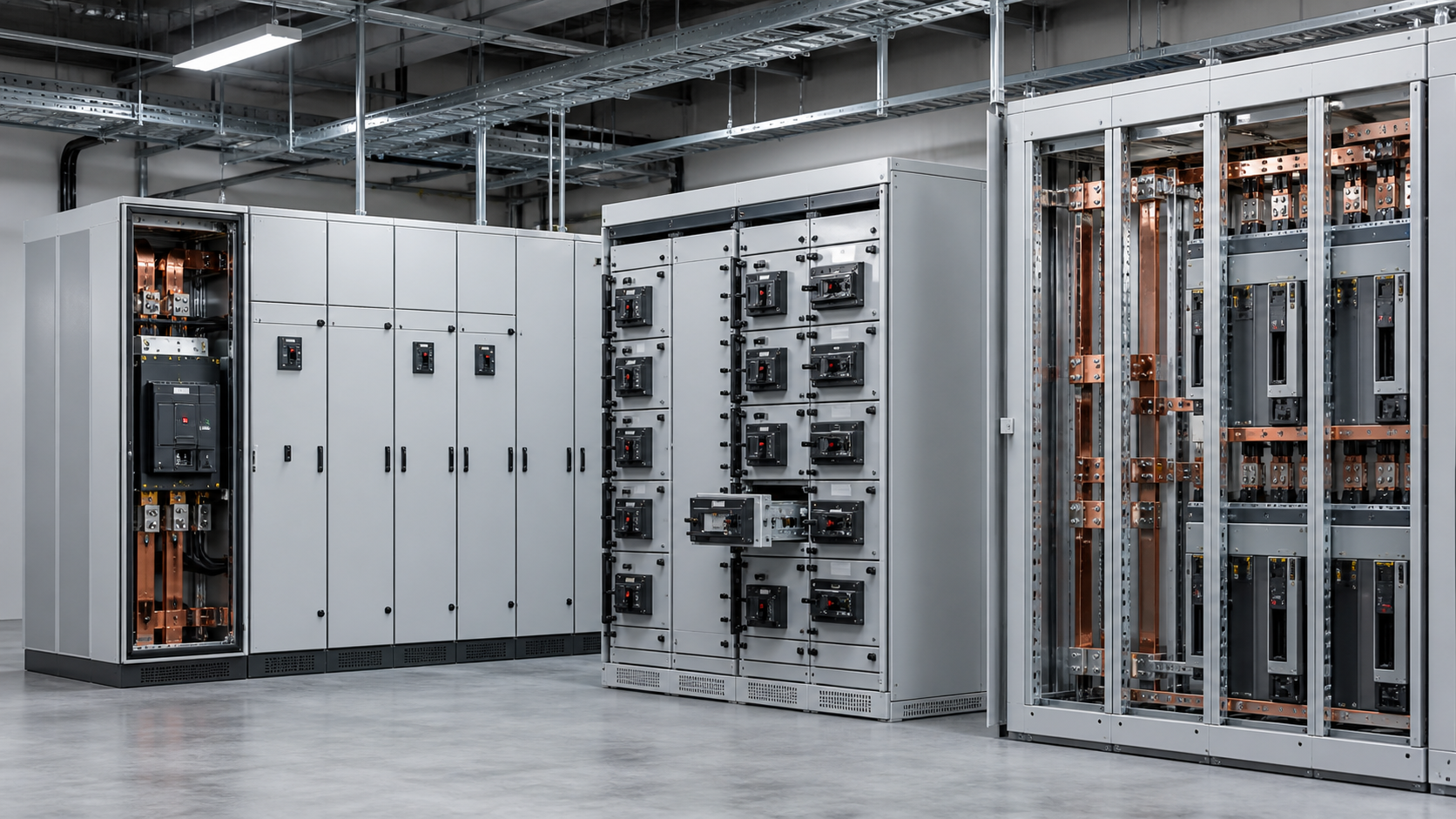
The ring main unit (RMU) is the switching and protection node of the MV collector network. Each inverter-fed compact substation or collector loop segment connects through an RMU, which provides load-break switching, fault isolation and a visible disconnect point. In a ring topology, an RMU lets an operator isolate a single faulty segment while the rest of the ring stays energized.
For a PV plant, RMUs are typically SF6-insulated or vacuum/solid-insulated metal-enclosed units rated for the collector voltage (commonly 33 kV / 35 kV). NEUTRON builds RMUs with integrated protection and remote signaling so the plant SCADA can locate and clear a collector fault without a site visit. A well-designed RMU layout keeps the collector ring serviceable during maintenance and limits outage spread.

Technical diagram shown at a readable responsive scale.
4. MV and LV switchgear coordination
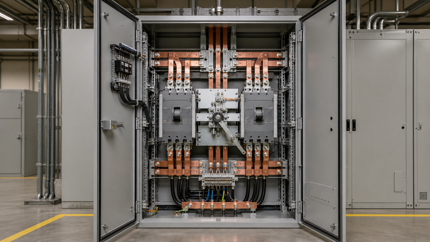
Switchgear coordination is what keeps a fault on one feeder from blacking out the plant. The coordination chain runs from the LV switchgear at each inverter, through the MV collector RMUs, to the step-up substation MV/LV switchboard:
NEUTRON low-voltage switchgear is built to IEC 61439 assemblies practice and integrates with the MV protection scheme, giving EPCs a coordinated LV-to-MV protection hierarchy rather than mismatched separate packages.
- LV switchgear isolates and protects each inverter AC output and the plant auxiliary loads.
- MV switchgear and RMUs protect the collector feeders and provide sectionalizing.
- Protection settings are graded so the nearest upstream device trips first, preserving the rest of the network.

Technical diagram shown at a readable responsive scale.
5. Protection, grounding and isolation
Large PV plants demand disciplined protection and grounding because of their scale and exposure. Key measures include:
Good isolation practice — combined with the disconnect and earthing switches inside the RMU and LV switchgear — is what lets crews work a collector segment safely while the plant keeps generating.
- Differential and overcurrent protection on the step-up transformer.
- Earth fault and feeder protection across the MV collector ring.
- A bonded earthing grid at the step-up substation and inverter stations to control step-and-touch potentials.
- Clearly visible isolation points at every RMU and switchboard for safe maintenance.
6. Prefabricated vs traditional substation
A traditional step-up substation is built on site: foundations, cable trenches, the transformer and switchgear are installed and wired in the field over many weeks. A prefabricated substation ships as a factory-tested enclosure or skid with the transformer, MV/LV switchgear and controls already integrated.
For most utility-scale PV plants, a prefabricated step-up substation paired with factory-built RMUs and LV switchgear shortens the critical path to grid energization, which is why NEUTRON positions prefabricated units as the default for PV distribution.
- Prefabricated: faster deployment, controlled factory testing, smaller site footprint, lower civil cost — ideal for PV plants on tight schedules.
- Traditional: more flexible for very large or unusual layouts, but longer build time and more on-site risk.
7. Standards (IEC 62271, IEC 61439, IEC 62271-202)
The equipment in a PV plant distribution backbone is governed by a clear set of IEC standards:
Specifying to these standards — and confirming them on the equipment datasheet — is what qualifies a substation for grid interconnection and keeps the plant insurable and serviceable over its life.
- IEC 62271 — high-voltage switchgear and controlgear, covering the MV RMUs and substation switchgear.
- IEC 61439 — low-voltage switchgear and controlgear assemblies, covering the LV switchboards and inverter ACDBs.
- IEC 62271-202 — AC prefabricated substations for rated voltages above 1 kV and up to and including 52 kV.
8. Specification checklist for EPCs
When an EPC issues an enquiry for a PV plant distribution package, the decisions that shape the design are:
Hand these parameters to the supplier and the step-up substation, RMUs and LV switchgear you receive will be engineered for the plant you are actually building. NEUTRON reviews the application context and prepares a configuration discussion around your project requirements.
- Collector network voltage (e.g. 33 kV / 35 kV) and grid interconnection voltage (110 kV / 220 kV / 400 kV).
- Plant capacity and number of inverter feeders driving the transformer and RMU count.
- Substation form: prefabricated vs traditional, and the transport/footprint limits of the site.
- Protection and grounding philosophy, including the earthing grid and fault grading.
- Switchgear standards and environmental rating (temperature, altitude, corrosion class).
This is general technical guidance. Final ratings, standard editions, protection coordination and compliance evidence must be confirmed for the actual project and applicable local requirements.
Frequently asked questions
What is a ring main unit in a PV plant?
A ring main unit (RMU) is the medium-voltage switching and protection node of the collector network. It connects inverter-fed feeders into a ring or radial layout and provides load-break switching, fault isolation and a visible disconnect point, so a single faulty segment can be isolated while the rest of the ring stays energized.
What does a step-up substation do?
A step-up substation raises the medium-voltage collector network of a PV plant to the grid transmission voltage through a main power transformer, and houses the switchgear, protection, metering and control needed to export energy safely. It is the interface between the plant and the grid.
Prefabricated vs traditional substation — which for PV?
For most utility-scale PV plants, a prefabricated substation is the better choice: it ships factory-tested, needs less civil work and reaches grid energization faster. A traditional built-on-site substation suits very large or unusual layouts but costs more time and on-site risk.
Which switchgear standards apply to PV plants?
The key standards are IEC 62271 for MV switchgear and RMUs, IEC 61439 for LV switchgear assemblies, and IEC 62271-202 for prefabricated high-voltage/low-voltage substations. These govern interconnection eligibility and long-term serviceability.
Bring the project inputs to the first review.
NEUTRON reviews the application context and prepares a configuration discussion around project requirements and the applicable document package.
Discuss a projectContinue learning
Explore related technical guidance in Power Distribution.
Technical note: confirm the applicable standard edition, project design basis, local requirements and evidence package before final equipment selection or release.