
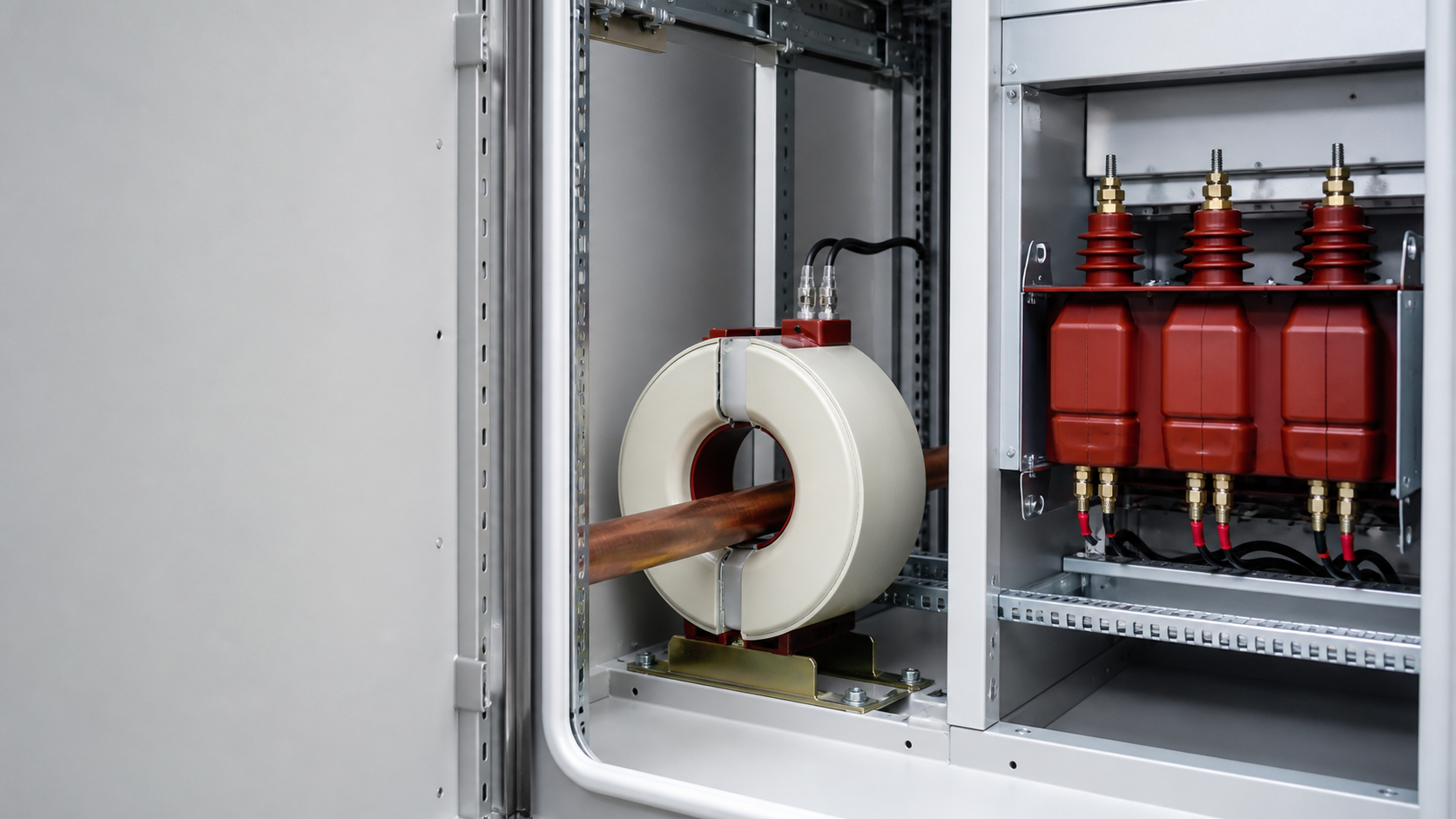
1. CT and PT defined in plain engineering terms
Both devices are instrument transformers. Their job is not to transfer power but to produce a scaled, isolated replica of a live quantity so that meters, protection relays and control equipment can work at safe, standardised levels.
A current transformer has a primary winding — often a single conductor or busbar passing through a toroidal core — and a secondary winding with many turns. Primary current creates flux in the core; the secondary delivers a proportional current, typically 5 A or 1 A at rated primary current. A ratio marked 600/5 A means 600 A of line current produces 5 A at the terminals of the connected instrument.
A potential transformer is a wound voltage transformer with a high-turn primary connected across the phases (or phase to earth) and a low-turn secondary. A ratio marked 10 000/100 V means 10 kV on the network appears as 100 V at the relay terminals. In IEC documents the same device is normally called a voltage transformer (VT); PT is the older term still common in tender specifications.
Because the CT is a current device and the PT is a voltage device, almost every other difference — winding design, connection, failure mode, protective treatment — follows from that single fact.
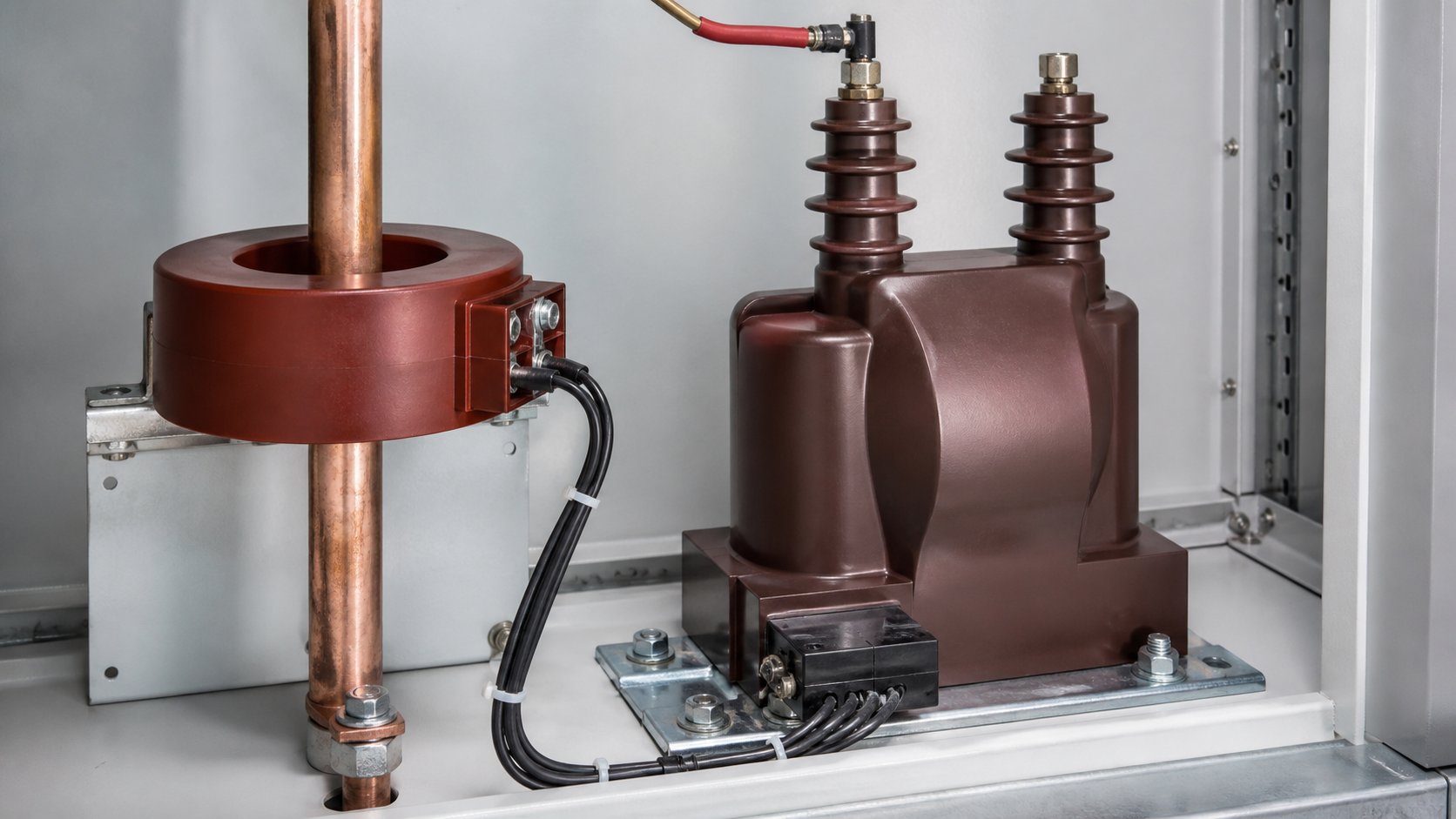
2. Connection, loading and failure behaviour
The connection method is the fastest way to tell the two apart on a single-line diagram.
This reverses their dangerous condition. Open the secondary of an energised CT and the core saturates hard; the flux collapse at each zero crossing produces peak voltages that can reach several kilovolts, destroying insulation and injuring the technician. Short the secondary of an energised PT and the primary sees a fault path, drawing heavy current until the protective fuse clears.
Practical rule for commissioning teams: short a CT secondary before you disconnect an instrument; fuse a PT secondary and never bridge it. NEUTRON metering cabinets are delivered with shorting terminal blocks on every CT circuit and secondary fuses on every VT circuit so the safe action is also the easy action.
- CT — series connection. The full load current of the feeder passes through the primary. The primary current is fixed by the load, not by the CT.
- PT — parallel connection. The primary sits across the line like a voltmeter. The primary voltage is fixed by the network.
- CT secondary is a near short-circuit by design. It works into a very low impedance (ammeter, relay coil, shorting link).
- PT secondary is a near open-circuit by design. It works into a very high impedance (voltmeter, relay voltage input).
| Title tag (50 chars) | Current Transformer vs Potential Transformer Guide |
|---|---|
| Meta description (154 chars) | Current transformer vs potential transformer: connection, ratios, accuracy class, burden and safety rules for switchgear and box-type substation projects. |
| Slug | what-is-the-difference-between-current-transformer-and-potential-transformer |
| Canonical | https://neutronele.com/insights/what-is-the-difference-between-current-transformer-and-potential-transformer |
| Primary keyword | difference between current transformer and potential transformer |
| Secondary keywords | CT vs PT, instrument transformer accuracy class, CT burden VA, voltage transformer ratio, IEC 61869 |
| Search intent | Informational / commercial investigation — engineers and buyers specifying instrument transformers for MV and LV assemblies |
| Schema type | Article + FAQPage + BreadcrumbList |
3. Ratings, accuracy class and burden compared
Tender documents usually fail on three parameters: ratio, accuracy class, and burden. Burden is the apparent power in VA that the secondary circuit can drive while staying inside its accuracy class. Long control cables add burden; undersized CTs then drift out of class and revenue metering is rejected at handover.
Table 1 — Current transformer vs potential transformer at a glance
Read the class suffix carefully. 0.5S holds its accuracy down to 1 % of rated current and is the class utilities demand for revenue metering on feeders with wide load swings; plain 0.5 is only guaranteed from 5 %. On the protection side, 5P20 means 5 % composite error at 20 times rated current — the CT still reports usefully during a fault instead of saturating.
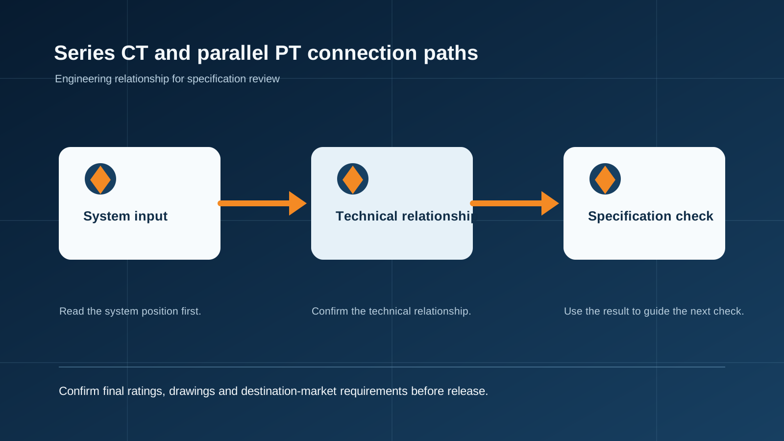
Technical diagram shown at a readable responsive scale.
4. Where CTs and VTs sit in NEUTRON assemblies
Instrument transformers are rarely bought alone. They arrive installed, wired and tested inside a switchgear panel, a metering cubicle or a box-type substation, and their ratings must match the assembly around them.
NEUTRON builds LV assemblies to IEC 61439-1/-2 and MV switchgear to IEC 62271-200, with instrument transformers selected to IEC 61869. Rated secondary values, burden, accuracy class, and thermal short-time current (Ith) are confirmed on the panel schedule before manufacturing starts.
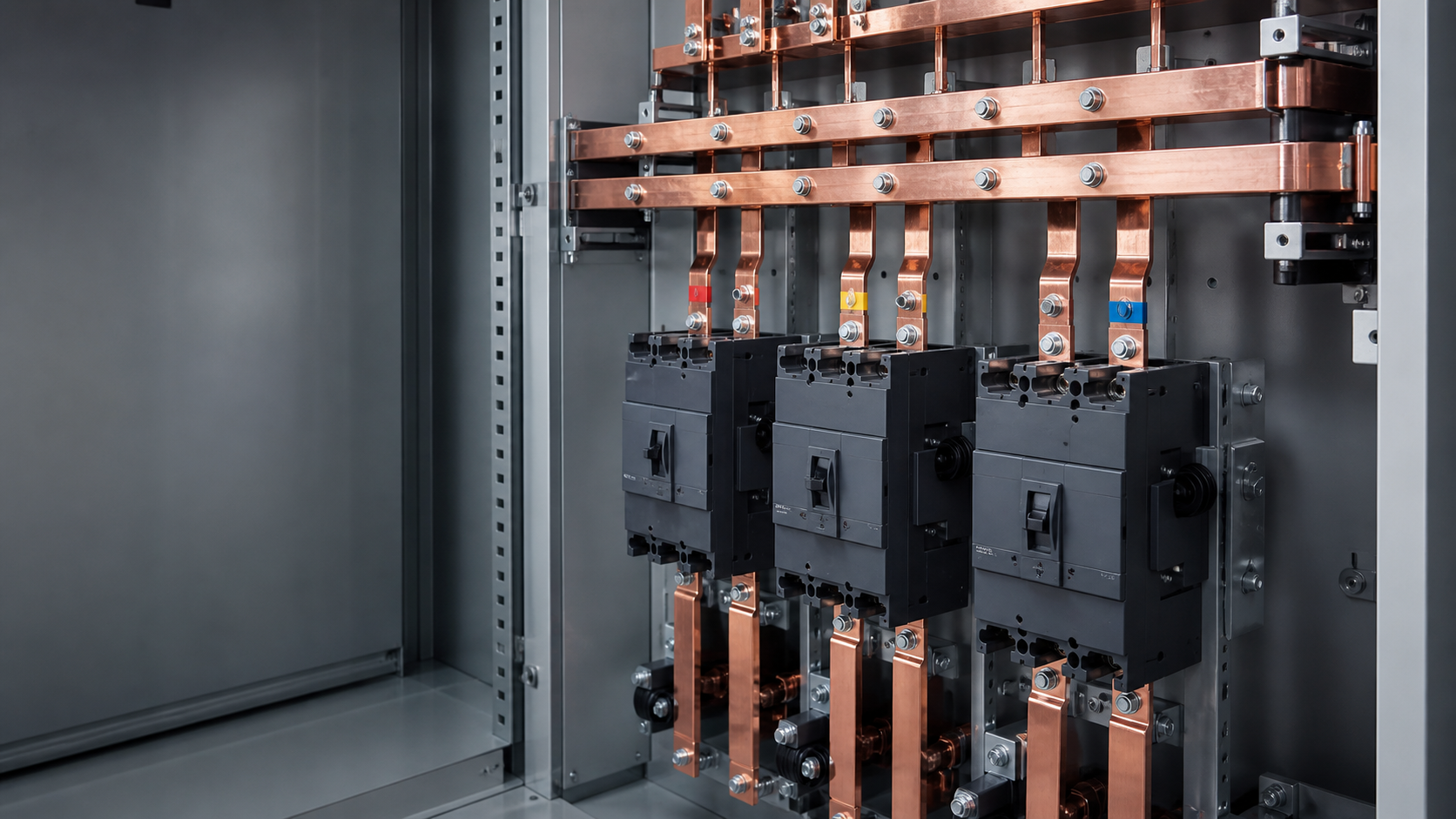
- LV distribution and feeder cabinets — CTs on incoming and outgoing ways feed the multifunction meters and the protection settings of the main air circuit breaker. NEUTRON intelligent frame-type breakers cover 200 A to 6300 A with 80 kA to 120 kA short-circuit breaking capability, so CT ratios and short-time thermal ratings are selected to survive the same fault level.
- Metering and incoming cubicles — combined CT/VT compartments with shorting blocks, test terminals and sealed covers for utility acceptance.
- Box-type substations — MV VTs supply the auxiliary and protection voltage circuits, while CTs on the transformer LV side feed the energy meter and the earth-fault protection relay.
- Compensation and power quality cabinets — CT position matters more than CT class: a reactive power controller reading the wrong CT will over- or under-compensate the whole installation.
5. Five mistakes that delay commissioning
Each of these is caught in a 20-minute design review. None of them is cheap to fix once the panel is on site and the utility inspector is waiting.
- Specifying ratio only. A line reading "800/5 A" without class and burden is not a specification. Always state ratio, class, VA and Ith / Idyn.
- Mixing 1 A and 5 A circuits. Import projects frequently arrive with 1 A relays and 5 A CTs. The meter reads a fifth of the real value and the error is often blamed on the transformer.
- Ignoring cable burden. 60 m of 2.5 mm² control cable on a 5 A secondary can consume more VA than the meter itself. Move to a 1 A secondary or increase the CT rating.
- Reversed polarity. P1/P2 and S1/S2 markings define the direction of measured power. Reversed polarity shows negative power flow, wrong directional protection and failed export metering.
- Treating a VT as a small power transformer. VT secondaries are for instruments. Feeding heaters, socket outlets or panel lighting from a VT ruins accuracy and can blow the primary fuse.
6. Safety, testing and standards compliance
Before energisation, the site team should confirm ratio and polarity by primary injection, verify the secondary loop resistance against the calculated burden, and check that all CT test links are closed and all VT fuses are correctly rated. Insulation resistance is measured between windings and to earth with the secondary circuits temporarily bonded.
Local wiring regulations always take precedence. Confirm the applicable national annex, the required accuracy class for billing, and any utility-specific approval list before the panel schedule is frozen.
- Secondary circuits must be earthed at one point only — normally the panel earth bar — to avoid circulating currents.
- Instrument transformer enclosures in outdoor kiosks and box-type substations follow the enclosure rating of the assembly, typically IP54 to IP65 depending on site conditions.
- Cast-resin units should be inspected for surface tracking and moisture ingress during scheduled maintenance.
- Every modification to a metering circuit must be re-sealed and recorded; utilities treat broken seals as tampering.
Media and assets
Placement plan for the /insights article template:
Subject: NEUTRON low-voltage switchgear line-up with a metering cubicle door open, ring-type current transformers visible on the copper busbar
Style: clean industrial B2B product photography
Details: grey powder-coated steel cabinets, tinned copper busbars, ring CTs mounted on the bars, neat secondary wiring in trunking, no visible branding
Background: plain light-grey studio sweep
Lighting: soft, even studio lighting, minimal shadows
Aspect ratio: 16:9
No text, no logos unless specified.
Subject: close-up of an instrument transformer secondary terminal area: CT shorting terminal block with test links plus a fuse carrier for the voltage transformer circuit
Style: clean industrial B2B product photography, macro detail
Details: numbered terminal strip, S1/S2 markings, grey DIN rail, ferruled control wires
Background: plain light-grey studio
- Hero image, 16:9, directly under the H1 — MV/LV switchgear line-up with metering cubicle in focus.
- Inline image after Section 2, 4:5 — close-up of a CT secondary shorting terminal block and VT fuse carrier.
- Inline technical diagram after Section 3, 1:1 — single-line diagram showing series-connected CT and parallel-connected VT.
- Table 1 rendered as a responsive three-column comparison table inside Section 3.
- CTA block at the end of the article, full width, with the quote button.
This is general technical guidance, not a substitute for local electrical code, the applicable standard, product datasheets or a qualified engineer's design review. Confirm ratings and final configurations against the actual project.
Frequently asked questions
What is the difference between a current transformer and a potential transformer?
A current transformer reduces line current to a measurable secondary current. A potential transformer reduces system voltage to a measurable secondary voltage.
Can a CT secondary be left open?
No. A current transformer secondary must be handled according to its instructions and the approved safety procedure; an open secondary can create a hazardous voltage.
What information is required to select an instrument transformer?
Confirm the primary system rating, secondary rating, accuracy class, burden, installation arrangement, insulation requirements and the measuring or protection function.
Bring the project inputs to the first review.
NEUTRON can review the application context, electrical envelope, enclosure conditions and document requirements related to what is the difference between current transformer and potential transformer before quotation.
Discuss a technical requirementContinue learning
Explore related technical guidance in Power Distribution.

Technical note: source article content is retained for educational use. Applicable standards, ratings, protection coordination and final configurations must be confirmed for the actual project and destination market.