
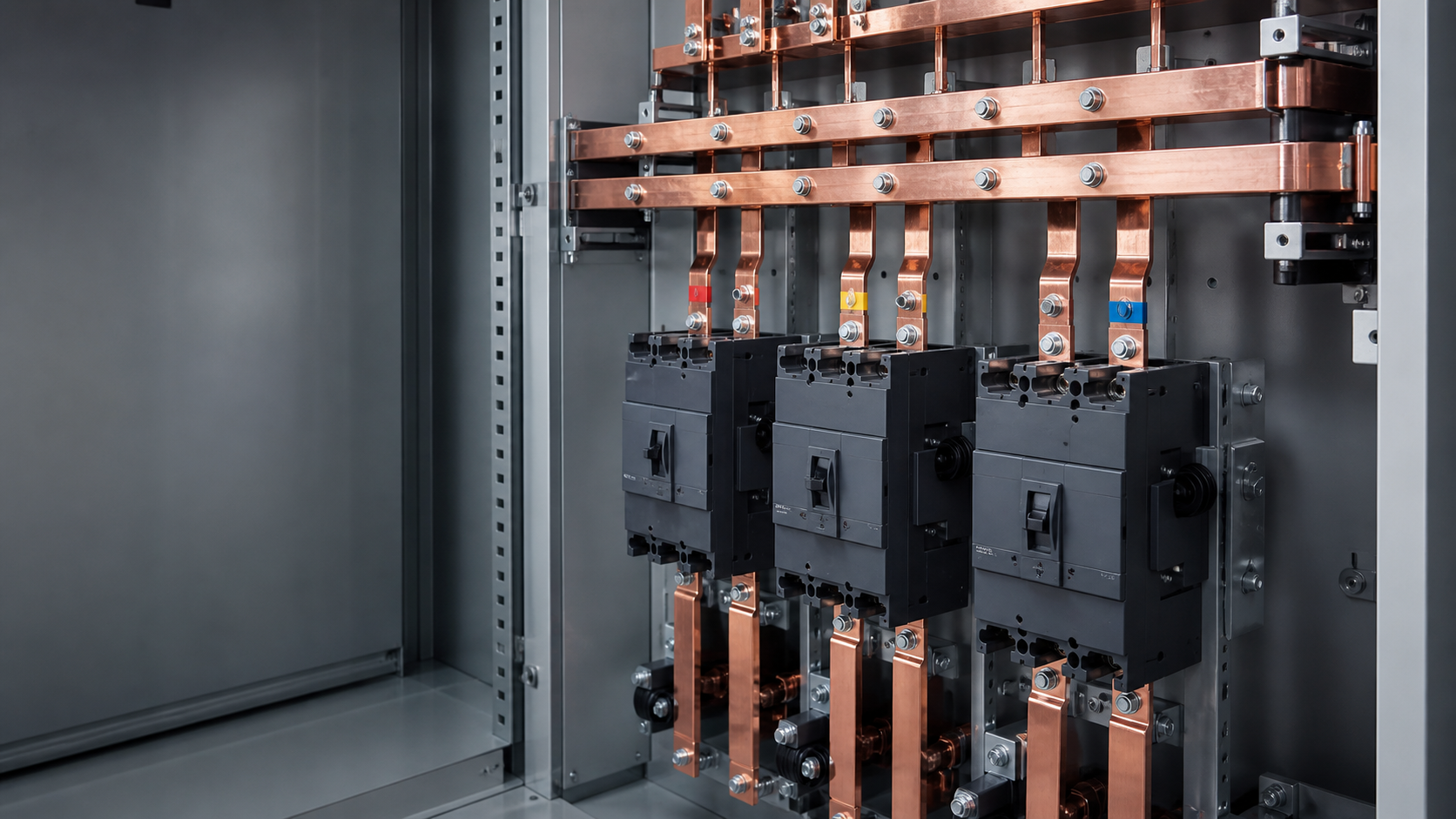
Busbar and circuit breaker: what each does
A busbar is a rigid electrical node. A circuit breaker interrupts its branch during overload or short circuit. Together they form the standard architecture of a distribution board: an incoming device feeds a busbar system, and outgoing breakers tap the common potential.
- Comb or pin busbar: insulated, moulded and pitched for DIN-rail devices.
- Panel busbar system: flat copper or aluminium bars supported inside a switchgear cabinet.
- The comb bar is a wiring accessory; the panel busbar is a structural part of the assembly.
Why busbar distribution is used
A properly engineered bar offers a large conductive cross-section and repeatable tap points. Compared with many jumper wires, it can reduce resistance, terminations and assembly variation. The trade-off is that support pitch, phase spacing, clearances and thermal expansion must be designed rather than improvised.
- Lower connection count and fewer potential loose-joint failures.
- More repeatable assembly and easier extension of outgoing ways.
- Better mechanical behavior under short-circuit forces when correctly supported.
- Predictable voltage drop and temperature-rise behavior when verified in the assembly.
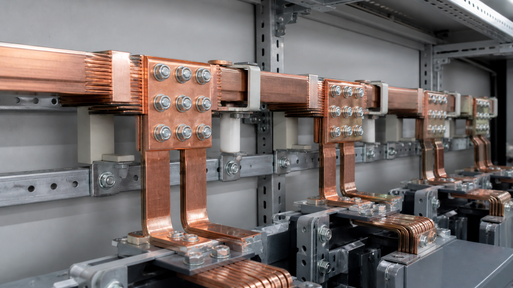
Copper, aluminium and plating
Copper provides high conductivity and compact joints. Aluminium can reduce weight and material cost, but its oxide layer, creep and joint preparation require careful treatment. Tinning can stabilize contact resistance and is useful in humid or coastal environments.
| Property | Copper | Aluminium |
|---|---|---|
| Conductivity | Higher reference conductivity | Lower; larger cross-section may be needed |
| Weight | Higher | Lower for an equivalent current duty |
| Joint preparation | Clean, torque correctly | Abrade, use joint compound and suitable bimetallic hardware |
| Typical use | Compact switchgear and high fault levels | Long or weight-sensitive runs when joints are engineered |
Sizing, ratings and verification
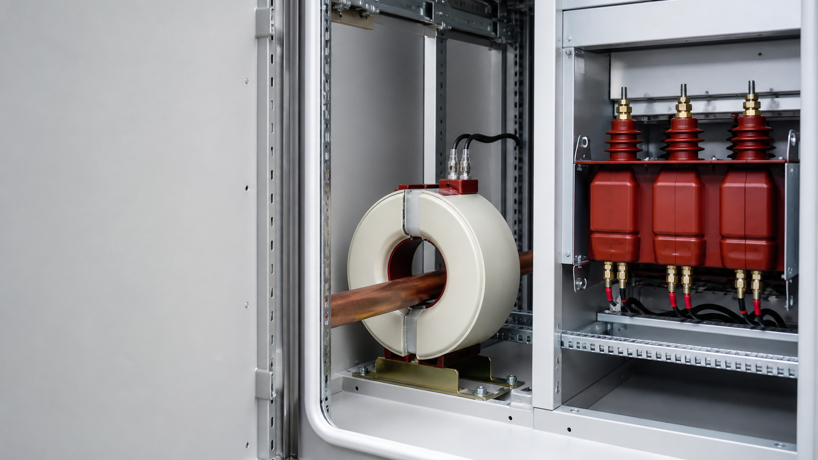
A busbar has two independent duties: carry continuous current without exceeding the permitted temperature rise, and withstand short-circuit forces without permanent deformation. Actual capacity depends on ambient temperature, enclosure ventilation, orientation, spacing, plating and parallel-bar arrangement.
- Icw: short-time withstand current, commonly stated for a defined duration.
- Ipk: peak withstand current that influences electromagnetic forces and support pitch.
- Temperature-rise limit: confirm the value and test basis for the supplied assembly.
- Neutral sizing: consider third-harmonic currents from LED drivers, drives and IT loads.
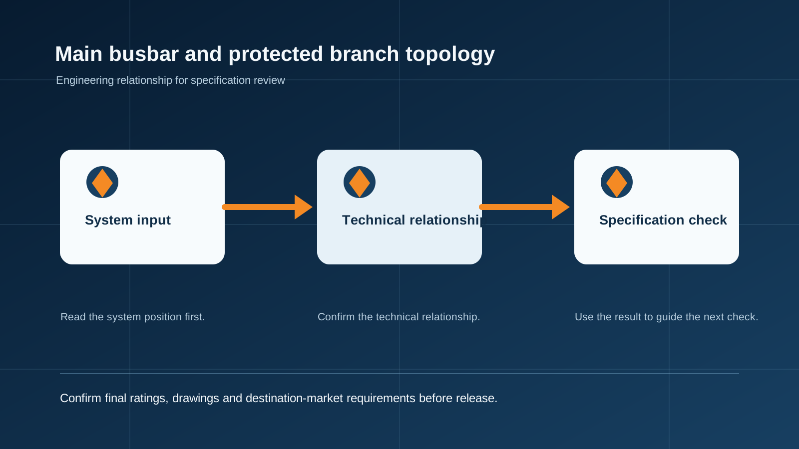
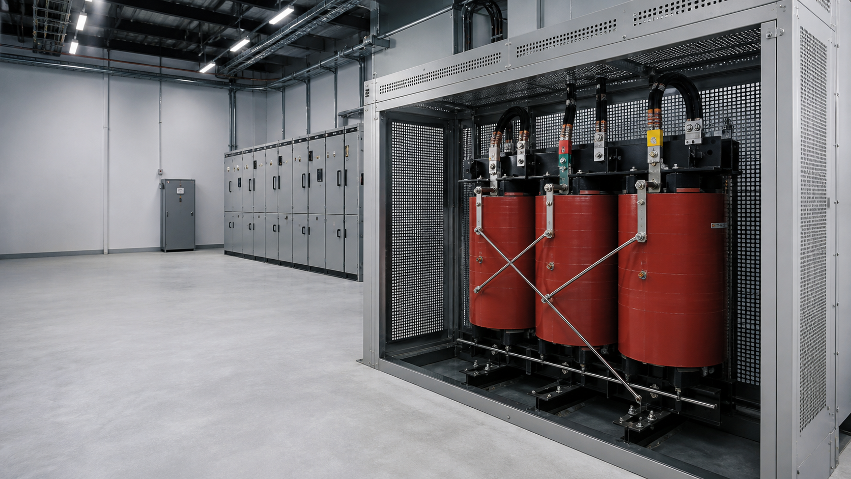
Technical diagram shown at a readable responsive scale.
Installation, torque and common mistakes
Use the specified torque and record bolted-joint checks. Do not mix copper and aluminium directly, remove structural supports to make room for cables, cut comb bars without fitting end caps, or assume added insulation replaces required clearances. Thermal imaging at handover and maintenance can reveal developing hot joints.
- Follow the support pitch and phase spacing.
- Keep live work under a documented risk assessment and permit system.
- Apply the applicable national wiring rules and assembly instructions.
- Recheck aluminium joints after initial thermal cycles where the design requires it.
Indicative busbar ratings are not approvals for a finished panel. Final temperature-rise and short-circuit performance depend on the exact assembly and must be verified by the responsible manufacturer or engineer.
Frequently asked questions
Is a busbar better than wiring for a distribution board?
For distributing current from one incoming point to several breakers, a properly engineered busbar usually offers fewer terminations and more repeatable behavior. Cables remain appropriate for many incoming and outgoing runs.
Should I specify copper or aluminium busbar?
Copper suits compact switchgear and high fault levels. Aluminium can suit long or weight-sensitive runs when oxide, creep, joint preparation and bimetallic interfaces are properly engineered.
How do I know the current rating of a busbar?
Published tables are starting points. The actual rating depends on the enclosure and arrangement, so temperature-rise verification for the supplied assembly is the evidence to request.
What is a comb busbar?
It is an insulated moulded bar with pins or forks that connect adjacent DIN-rail devices. It replaces multiple jumper wires, but exposed cut ends must be protected with the correct end caps.
Review busbar current and fault duty
Share rated current, prospective fault current, ambient conditions, enclosure form and required separation so the busbar material, supports and verification basis can be reviewed.
Request a quoteContinue learning
Explore related technical guidance in Power Distribution.

This guide is general application guidance. Final ratings, protection coordination, standards evidence, installation and local code compliance must be confirmed against the actual project and destination-market requirements by qualified personnel.