
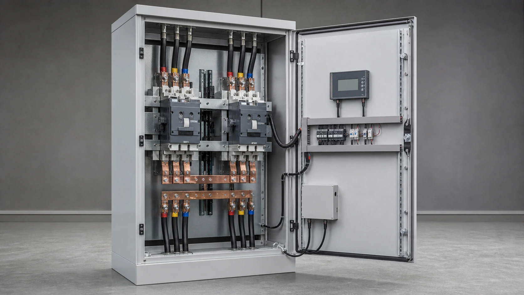
What a Changeover Switch Actually Does
A changeover switch has two inputs and one output. The load is connected to the normal supply or the standby supply, never both in a standard open-transition arrangement.
The reason is safety: accidental paralleling can backfeed a generator or create an out-of-phase reconnection. A proper device uses mechanical and electrical interlocking, plus a defined both-open state where both supplies are disconnected.
- Two inputs and one output.
- Defined neutral treatment, with 3-pole or 4-pole selection based on the system.
- Positive mechanical and electrical interlocking.
- Full-load current and inrush duty considered in the rating.
How an Automatic Changeover Works
An automatic unit monitors phase presence, phase sequence and voltage on both supplies. When it detects loss, phase failure, undervoltage or overvoltage, the controller opens the faulty source, moves through the both-open state and closes onto the healthy source after the configured delay.
The supplied source describes motor-driven mechanisms, position feedback, an LCD controller, alarm records and adjustable transfer and recovery delays. The actual thresholds, delays and controller supply must be confirmed for the selected model.
Manual vs Automatic; Open vs Closed Transition
Manual changeover switches suit small attended installations where an operator can act and a short outage is acceptable. Automatic transfer switches are used where unattended recovery or availability matters.
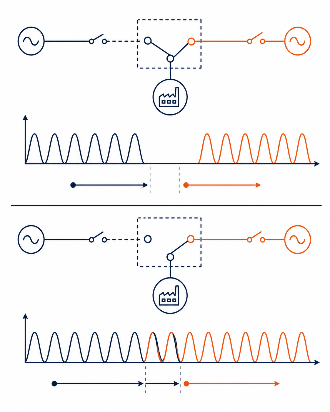
Open transition breaks the first source before making the second and creates a short dead interval. Closed transition makes the second source before breaking the first, briefly paralleling the sources. It requires synchronising equipment and written network-operator approval. Delayed transition adds a deliberate dwell in the both-open state for loads such as large motors.
NEUTRON Dual-Supply Transfer Switches
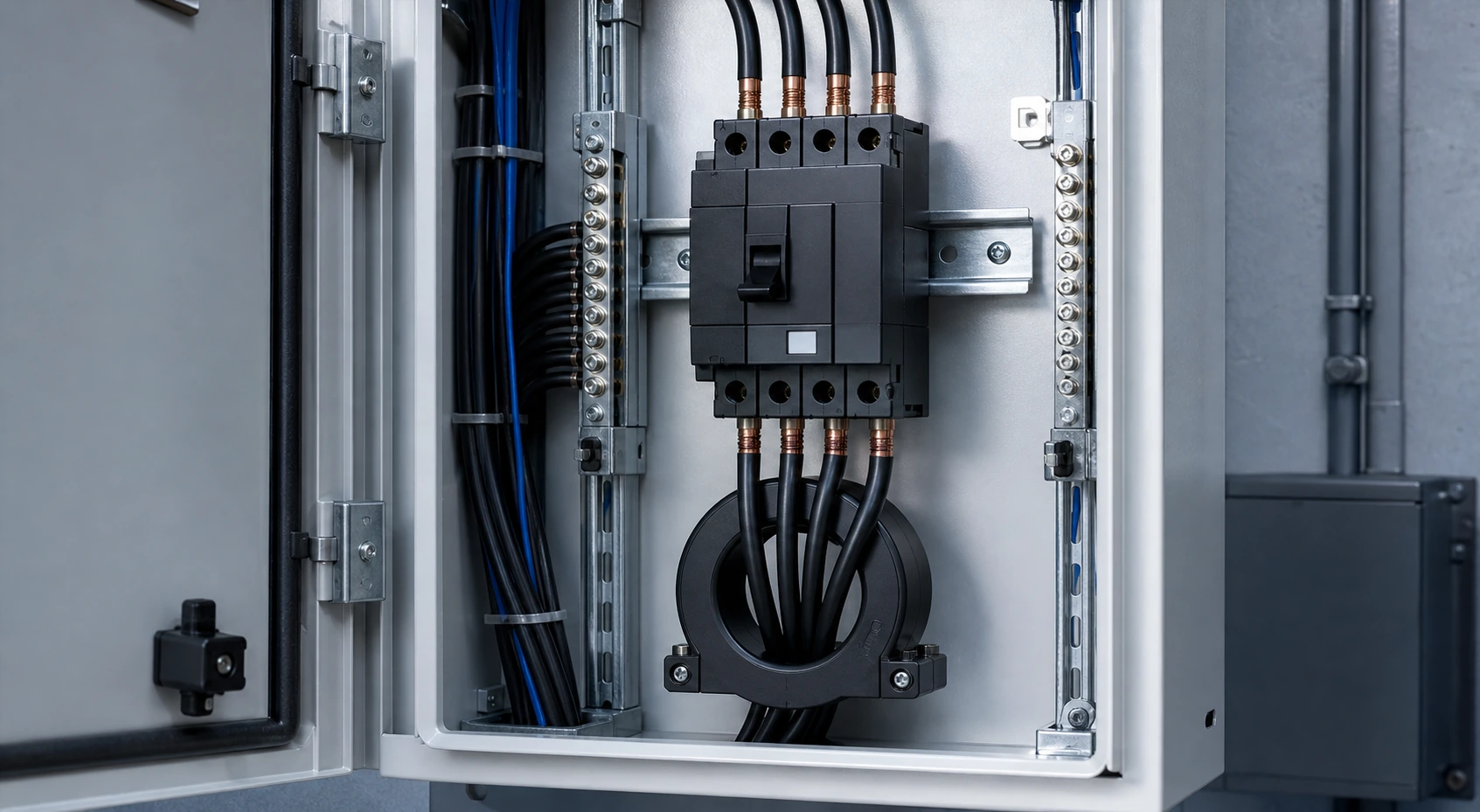
The supplied source describes the NEUTRON WCQ2 series as an intelligent dual-supply automatic transfer switch for 400 V, 50 Hz systems, with current frames from 16 A to 2000 A and 3P or 4P configurations depending on the frame. It also describes adjustable delay, auto-recovery or non-auto-recovery, LCD settings and loose or cabinet-integrated supply. Confirm the model data and evidence for the quoted configuration.
| Selection item | Why it matters |
|---|---|
| Rated current | Must carry the continuous load and withstand the installation fault level |
| Poles | Neutral switching depends on earthing and residual-current protection |
| Transition | Open, delayed or closed transition changes the interruption and approval requirements |
| Controller supply | Must remain available for monitoring and transfer logic |
| Mechanical life | Should match the expected transfer frequency and maintenance plan |
How to Size and Select
- Start from maximum continuous load current and prospective short-circuit current, not generator nameplate alone.
- Choose 3P or 4P after checking the standby earthing arrangement and downstream residual-current protection.
- Check motor and transformer inrush and the ability to make onto the load.
- Confirm the controller supply, including whether a UPS is needed when both sources can be unavailable.
- Set realistic transfer and recovery delays so the system does not hunt on an unstable network.
- Plan inspection around the expected number of operations.
Installation and Safety Notes
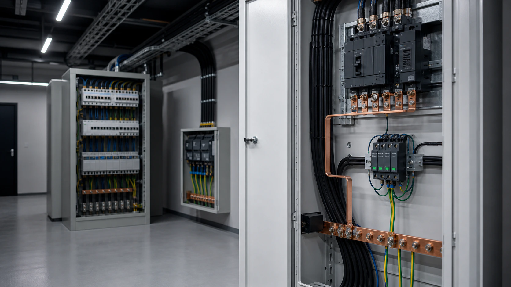
The source describes installation away from rain, snow, explosive atmospheres, conductive dust and corrosive gases, with the ambient and altitude limits of the selected product observed.
- Never bypass the mechanical interlock.
- Verify phase sequence on both feeds before commissioning.
- Label the intake position clearly for emergency isolation.
- Test transfer and re-transfer under the actual load at handover and during scheduled maintenance.
- Follow local wiring and utility connection rules where they are more demanding.
Transfer equipment is safety-critical. The approved single-line diagram, earthing arrangement, utility rules, generator behavior and qualified commissioning work control the final selection.
Frequently asked questions
What is the difference between a changeover switch and a transfer switch?
In common electrical usage they describe the same two-source switching function. Changeover is common in several export markets; transfer switch or ATS is common in North American and IEC product language.
How long does an automatic transfer take?
The mechanism can move quickly, but the controller delay, generator start and source stabilisation determine total restoration time. The selected controller may allow an adjustable delay.
Should I choose 3-pole or 4-pole?
Use the earthing arrangement, neutral treatment, downstream residual-current protection and local requirements to decide. A 4-pole device separates the neutral as well as the phases.
Can a changeover switch parallel the generator with the utility?
Only a closed-transition arrangement can do so, and only with synchronising equipment and written approval from the network operator. Standard open-transition devices are interlocked against paralleling.
What standard applies to an ATS?
The supplied source references IEC 60947-6-1 and GB/T 14048.11 for transfer equipment, with IEC 61439-1/-2 relevant to the surrounding assembly. Confirm the applicable edition and scope.
Start with the Two Sources and the Load
Share the load current, pole requirement, fault level, standby source and transition preference so the transfer switch and cabinet arrangement can be reviewed together.
Request a quoteContinue learning
Explore related technical guidance in Electrical Protection.

Adapted from the supplied DOCX. NEUTRON WCQ2 ratings and standards statements are source-provided and should be verified against the actual model and market.