
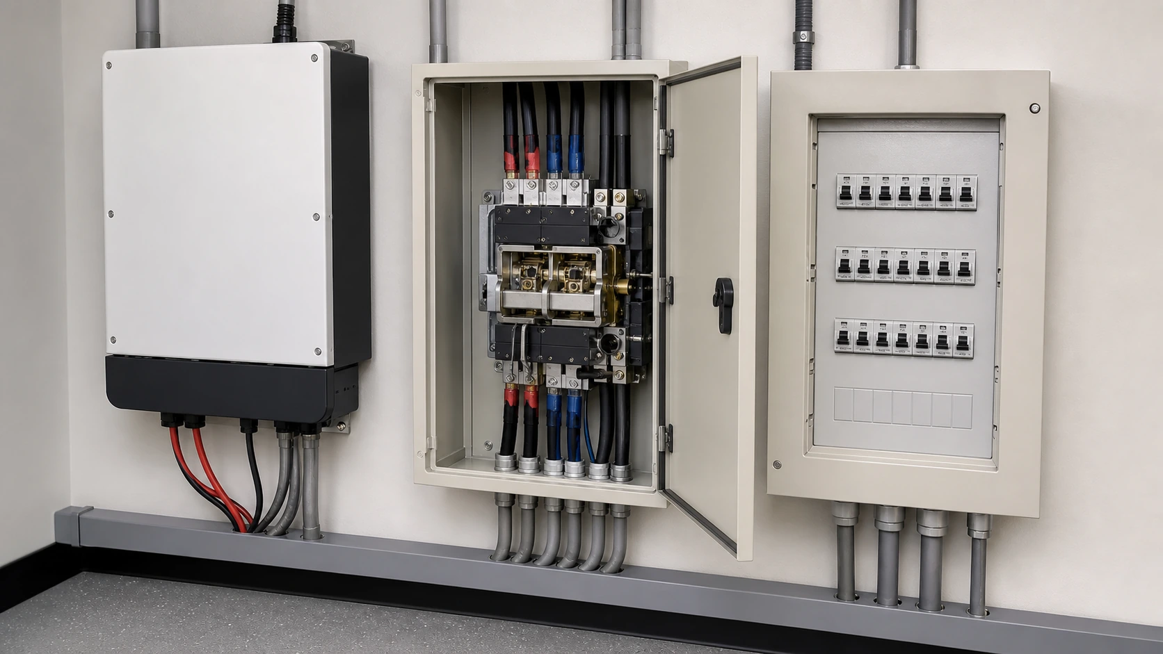
1. Why a Grid-Tied Array Stops When the Grid Goes Down → #solar-transfer-switch-explained-1-paradox
Review the project requirements and the applicable documentation for 1. why a grid-tied array stops when the grid goes down → #solar-transfer-switch-explained-1-paradox.
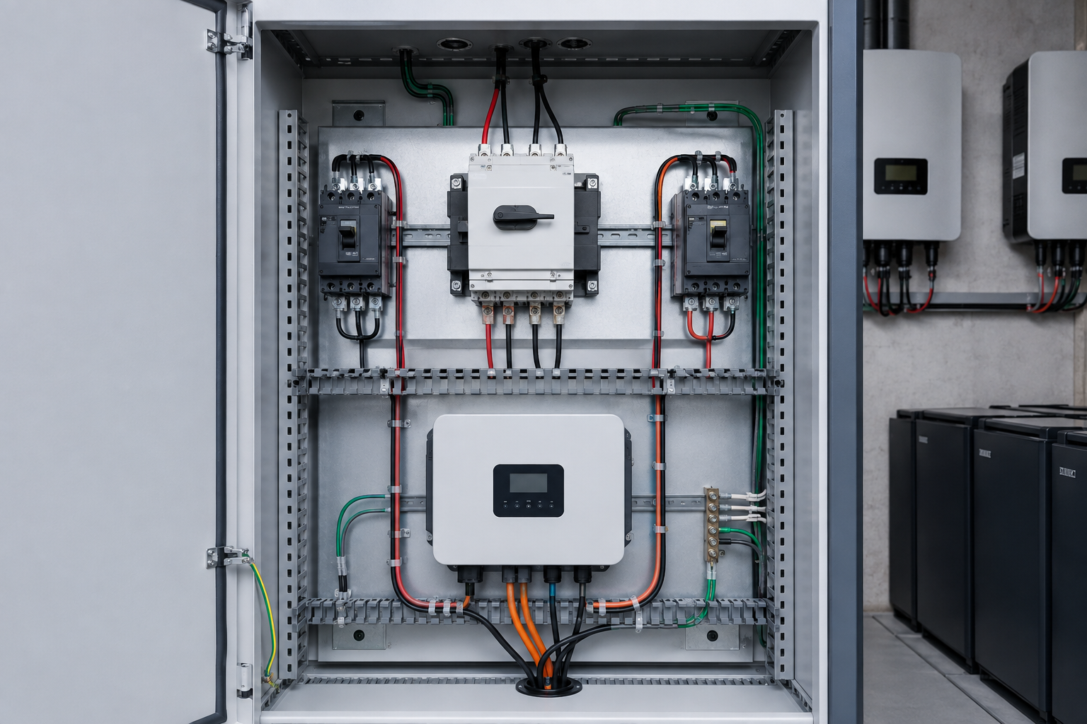
2. Anti-Islanding: The Safety Logic Behind the Shutdown → #solar-transfer-switch-explained-2-anti-islanding
Review the project requirements and the applicable documentation for 2. anti-islanding: the safety logic behind the shutdown → #solar-transfer-switch-explained-2-anti-islanding.
| Criterion | Manual transfer switch (MTS) | Automatic transfer switch (ATS) |
|---|---|---|
| Operation | Operator throws the handle on site | Controller senses and transfers unattended |
| Typical transfer time | Minutes to hours, depends on attendance | Seconds, adjustable by time delay |
| Typical ratings | 63 A to 250 A | 63 A to 3200 A |
| Pole configuration | 2P / 3P / 4P | 2P / 3P / 4P, neutral overlapping available |
| Control | None | Programmable voltage, frequency and delay windows |
| Monitoring | Position indication only | RS485 / Modbus RTU, status contacts, event log |
| Unattended sites | Not suitable | Standard choice |
| Relative cost | Low | Higher, offset by avoided downtime |
3. What a Solar Transfer Switch Actually Does → #solar-transfer-switch-explained-3-what-it-does
Review the project requirements and the applicable documentation for 3. what a solar transfer switch actually does → #solar-transfer-switch-explained-3-what-it-does.
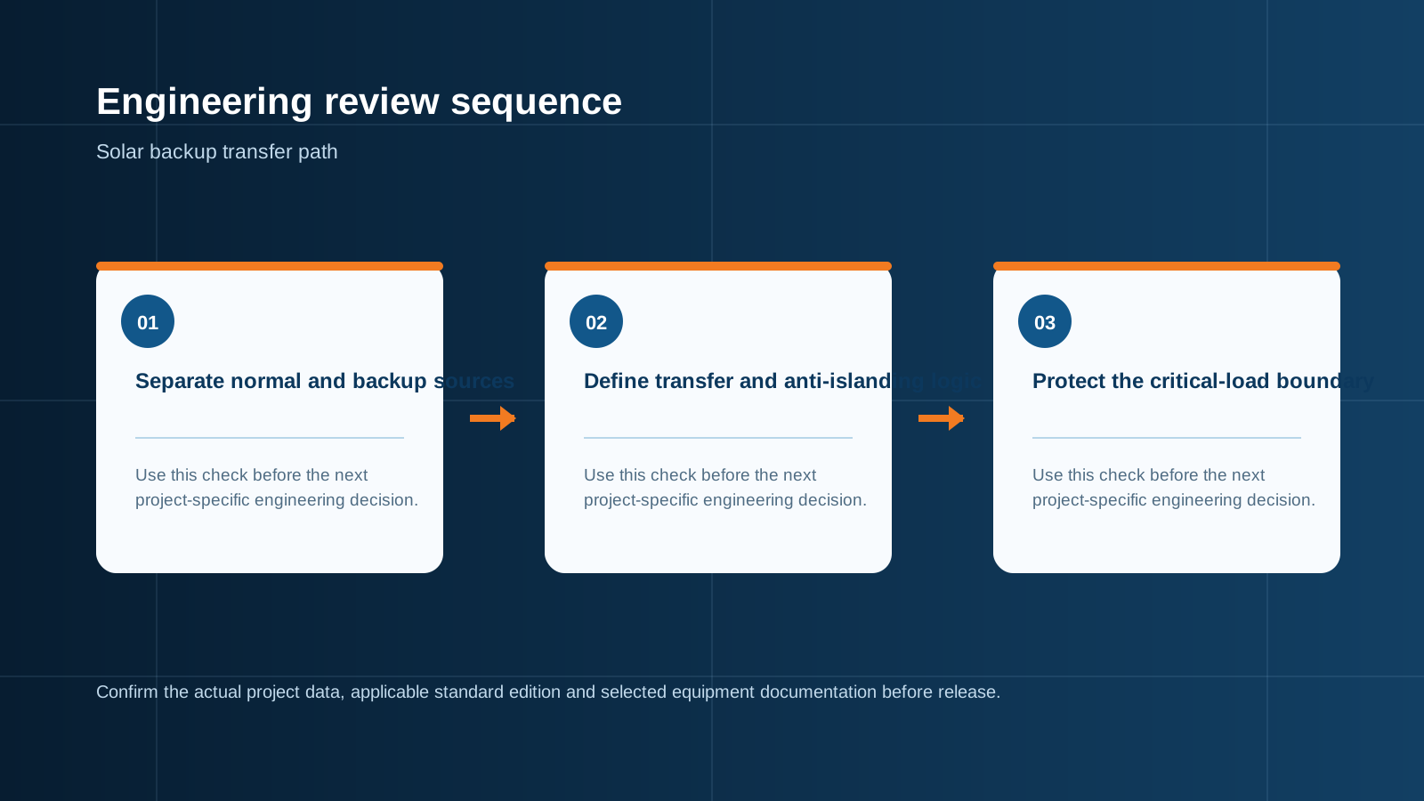
Technical diagram shown at a readable responsive scale.
4. Manual vs Automatic Transfer Switches → #solar-transfer-switch-explained-4-manual-vs-auto
Review the project requirements and the applicable documentation for 4. manual vs automatic transfer switches → #solar-transfer-switch-explained-4-manual-vs-auto.
5. The Critical Loads Sub-Panel → #solar-transfer-switch-explained-5-critical-loads
Review the project requirements and the applicable documentation for 5. the critical loads sub-panel → #solar-transfer-switch-explained-5-critical-loads.
6. Why a Switch Alone May Not Be Enough → #solar-transfer-switch-explained-6-storage
Review the project requirements and the applicable documentation for 6. why a switch alone may not be enough → #solar-transfer-switch-explained-6-storage.
7. Technical Checklist for Choosing the Switch → #solar-transfer-switch-explained-7-checklist
- FAQ → #solar-transfer-switch-explained-faq
1. Why a Grid-Tied Array Stops When the Grid Goes Down
It is the question every solar owner asks after their first blackout: the sun is shining, the modules are clean, and the house is dark. The array has not failed. The inverter has deliberately shut itself down.
A grid-tied inverter is designed to follow the utility waveform. It measures grid voltage and frequency continuously and synchronises its output to them. When the utility supply disappears, there is no reference waveform to follow and no defined limit on what the inverter would be asked to feed. Continuing to export in that condition would energise the local network from the customer side — an **island** of live conductors inside a network that operators believe is dead.
So the inverter disconnects, typically within a fraction of a second. Everything behind the meter goes dark even though generation capacity is sitting on the roof. Fixing that requires changing the topology of the installation, not the inverter settings.
2. Anti-Islanding: The Safety Logic Behind the Shutdown
Anti-islanding is a protection function required by grid codes worldwide and verified during type testing of inverters and grid-connected equipment. Its purpose is straightforward: protect the people who repair the network.
Consider a distribution feeder that has been isolated for maintenance. A line worker earths the conductors and starts work. If a customer's inverter were still exporting into that feeder, the low-voltage side could be live, and through a distribution transformer the medium-voltage side could be back-energised at several kilovolts. Anti-islanding removes that possibility.
Detection methods combine passive and active techniques — over/under voltage and frequency windows, rate-of-change-of-frequency monitoring, and small deliberate perturbations of the output that destabilise quickly when the grid reference is absent. The relevant framework includes **IEC 62116** for islanding prevention test methods, **IEC 61727** for utility interface requirements, and **IEEE 1547** in North American markets. Grid-connected cabinets built to **IEC 61439-2** carry the interface protection at the plant level for larger installations.
3. What a Solar Transfer Switch Actually Does
A transfer switch is a mechanically interlocked device that connects a load to one of two supplies and makes it physically impossible to connect both at once. In a solar backup installation, supply one is the utility feed and supply two is the backup path — a battery inverter, a generator, or a combination of the two.
The interlock is the whole point. Once the switch has moved the load to the backup path, the installation is a genuine electrical island with a defined boundary, so the inverter can safely form its own voltage and frequency reference. Back-feed into the utility network is prevented by hardware, not by software.
- **Isolation:** a visible, mechanically enforced separation between the utility feed and the backup path.
- **Automatic detection:** on an automatic unit, voltage and frequency sensing on both supplies with programmable thresholds and time delays.
- **Controlled re-transfer:** return to utility only after the grid has been stable for a set period, avoiding damage from repeated brownout cycling.
- **Load definition:** the switch feeds the critical loads sub-panel rather than the whole installation.
4. Manual vs Automatic Transfer Switches
Both types do the same electrical job. The difference is who decides, and how fast.
Table: Manual vs automatic transfer switch for solar backup
For a residence where somebody is usually home, a manual switch is defensible and inexpensive. For anything with unattended critical load — a cold store, a telecom cabinet, a water pumping station — the automatic unit is the only sensible specification, because the value of the equipment being protected exceeds the price difference within a single event.
5. The Critical Loads Sub-Panel
Backing up an entire installation is usually the wrong target. Inverter and battery capacity are sized in kilowatts, and an air-conditioning compressor or an electric water heater can consume the entire budget on its own.
The standard solution is a **critical loads sub-panel**: a second distribution board fed from the backup side of the transfer switch, containing only the circuits that must survive an outage. Everything else stays on the utility-only board and simply goes dark.
NEUTRON builds critical-load distribution boards and ATS cabinets to **IEC 61439**, in powder-coated cold-rolled steel enclosures from IP30 indoor to IP65 outdoor, with copper busbar and the breaker configuration specified by the project.
- Typical residential selection: refrigeration, lighting, communications, a small number of socket circuits, heating controls and the well pump where present.
- Typical commercial selection: emergency lighting, servers and network equipment, access control, refrigeration, process controllers and the fire alarm supply.
- Motor loads need attention: starting current can be several times running current, so the sub-panel total must be assessed on inrush, not nameplate.
- Label the sub-panel clearly and keep a schedule inside the door — during an outage, nobody has time to trace circuits.
6. Why a Switch Alone May Not Be Enough
A transfer switch defines the boundary. It does not create energy. What powers the critical loads once the island is formed depends on what sits behind the switch.
**With battery storage.** A hybrid or off-grid capable inverter forms its own voltage and frequency reference from the battery, and the array recharges that battery during daylight. This is the configuration that delivers a seamless, round-the-clock experience, and it is why battery storage and transfer switching are usually purchased together.
**Without battery storage.** Some inverters offer a limited daylight-only backup outlet, typically 1.5 kW to 3 kW, available only while irradiance is sufficient. Output collapses when a cloud passes and disappears at sunset. It will run a laptop, a router and a fan. It will not run a building.
**With a generator.** A generator behind the transfer switch is still the most common backup arrangement in commercial and industrial work. Here the switch has to manage a real machine: allow a start signal, wait out the warm-up period, and apply a delay on re-transfer so the set can cool under no load before shutdown.
7. Technical Checklist for Choosing the Switch
Two final practical points. Local wiring rules govern earthing and neutral treatment on the backup side, and they differ significantly between markets — confirm them before ordering rather than at inspection. And test the switch under load at least annually; a transfer switch that has never operated is an assumption, not a protection.
- **Current rating:** size to the critical loads sub-panel total with margin, and verify the rating is declared for continuous duty at the ambient temperature of the installation position.
- **Voltage and frequency:** 230 V single phase or 400 V three phase, 50 Hz or 60 Hz as applicable to the destination market.
- **Pole configuration:** 2-pole for single phase; 3-pole where the neutral is solidly bonded throughout; 4-pole where the neutral must be switched to keep earthing arrangements separate between supplies.
- **Transition mode:** open transition suits most solar backup work; delayed transition protects motor and inductive load from out-of-phase reconnection.
- **Short-circuit withstand:** confirm the rated short-time withstand current of the switch against the prospective fault current at its point of installation.
- **Enclosure:** IP30 or IP40 indoor, IP54 to IP65 outdoor, in powder-coated steel or stainless steel for coastal sites.
- **Standards:** the switch to **IEC 60947-6-1**, the assembly to **IEC 61439**, with **CE** and **CB** documentation and an **ISO 9001** manufacturer.
- **Commissioning:** confirm transfer and re-transfer timing under real load, and record the settings in the handover file.
Media & Assets
IMAGE PROMPT — Hero:
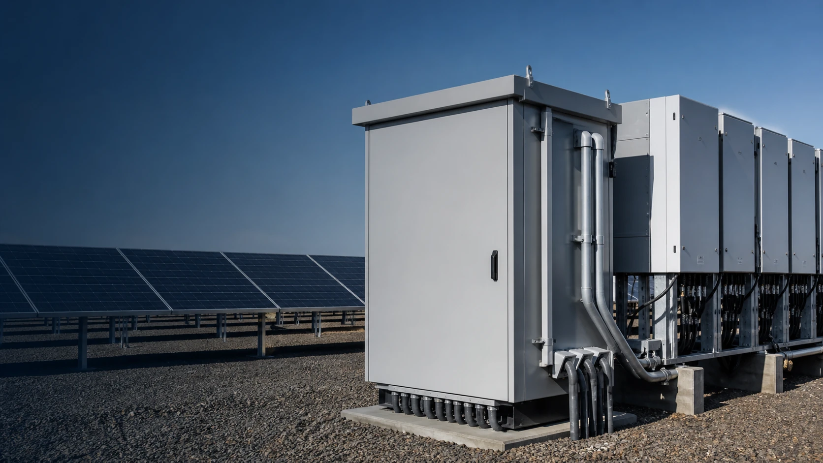
Subject: NEUTRON wall-mounted automatic transfer switch cabinet installed next to a hybrid solar inverter and a critical loads distribution board in a plant room
Style: clean industrial B2B product photography
Details: grey powder-coated steel enclosure with door open, four-pole transfer switch, controller with digital display, labelled utility and backup cables entering through glands
Background: clean plant room wall with conduit runs
Lighting: soft even indoor lighting
Aspect ratio: 16:9 (hero)
No text, no logos unless specified.
Alt text: NEUTRON automatic transfer switch cabinet beside a hybrid solar inverter
IMAGE PROMPT — Section 3:
Subject: single-line diagram of a solar backup installation with a transfer switch
Style: technical line diagram, flat vector, two-colour
Details: utility feed and battery inverter shown as two inputs to a mechanically interlocked transfer switch, output to a critical loads sub-panel, PV array and battery on the backup side, grid isolation boundary highlighted
Background: plain white
- Hero image: 16:9 at the top of the article, above the Key takeaway block.
- Inline image 1 (16:9 diagram): inside Section 3, showing the switch between utility, backup and load.
- Inline image 2 (4:5): inside Section 4, next to the manual vs automatic table.
- Inline image 3 (1:1): inside Section 5, showing the critical loads sub-panel.
- Apply loading="lazy" and descriptive alt text to every image.
FAQ
Q: Why do my solar panels stop working during a power cut?
A: The inverter shuts down deliberately. Anti-islanding protection prevents it from energising a network that utility crews may be working on. Production resumes automatically when the grid returns, unless a transfer switch and backup path have been installed.
Q: Can I add a transfer switch to an existing grid-tied system?
A: Usually yes, but the inverter must be capable of forming its own voltage and frequency reference when islanded. A conventional grid-following inverter needs to be replaced with, or supplemented by, a hybrid or off-grid capable unit before a transfer switch delivers useful backup.
Q: What is the difference between a manual and an automatic transfer switch?
A: A manual switch is thrown by an operator on site; an automatic switch senses supply failure and transfers unattended within seconds using programmable voltage, frequency and delay settings. Unattended critical load should always use an automatic unit.
Q: Do I need batteries as well as a transfer switch?
A: For continuous backup, yes. Without storage, some inverters provide a limited daylight-only backup outlet of roughly 1.5 kW to 3 kW that varies with irradiance and stops at sunset. Batteries are what allow the critical loads sub-panel to run through the night.
Q: Should I choose a 3-pole or 4-pole transfer switch?
A: Use 3-pole where the neutral is solidly bonded and common to both supplies. Use 4-pole where the neutral must be switched to keep the earthing arrangements of the two supplies separate, which is common where a generator has its own earth reference. Local wiring rules decide.
Q: How often should a transfer switch be tested?
A: At least annually under real load, with a record of transfer and re-transfer timing. Also verify the controller settings, check terminal torque, and inspect the enclosure seals if the unit is mounted outdoors.
Call to action
NEUTRON manufactures ATS cabinets, critical-load distribution boards, PV combiner boxes and grid-connected cabinets to IEC 61439 and IEC 60947-6-1, from 63 A to 3200 A. Send your load schedule and site conditions for a configured proposal.
Structured Data (JSON-LD)
Place the following block in the page <head> or the CMS schema field. Do not edit the values.
CODE: application/ld+json
"@context": "https://schema.org",
"@graph": [
"@type": "BreadcrumbList",
"itemListElement": [
"@type": "ListItem",
"position": 1,
"name": "Home",
"item": "https://neutronele.com/"
"@type": "ListItem",
"position": 2,
"name": "Insights",
"item": "https://neutronele.com/insights/"
Engineering decision map
Use this compact sequence to review the approved guidance in order. Confirm actual ratings, interfaces, applicable standard editions and selected equipment documentation before final specification or release.
Technical diagram shown at a readable responsive scale.
This is general technical guidance, not a substitute for local electrical code, the applicable standard, product datasheets or a qualified engineer's design review. Confirm ratings and final configurations against the actual project.
Bring the project inputs to the first review.
NEUTRON can review the application context, electrical envelope, enclosure conditions and document requirements related to solar transfer switch guide: why grid-tied systems fail in outages before quotation.
Discuss a technical requirementContinue learning
Explore related technical guidance in Solar PV.

Technical note: source article content is retained for educational use. Applicable standards, ratings, protection coordination and final configurations must be confirmed for the actual project and destination market.