
1. Why PV plus storage plants are growing
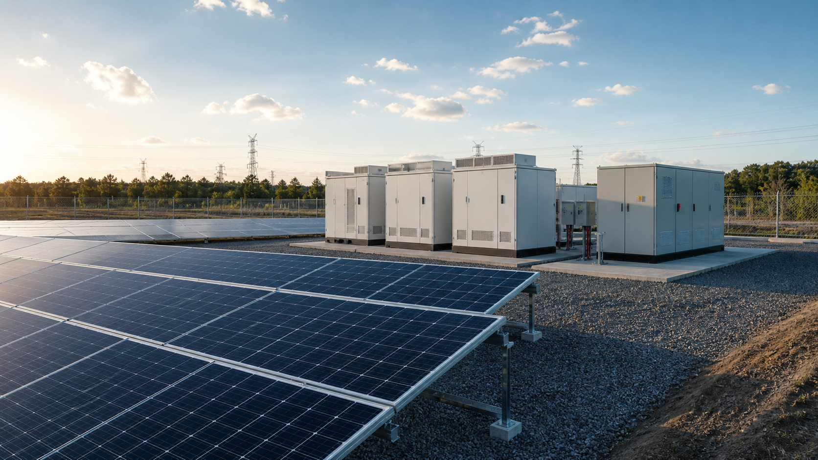
Grid operators increasingly ask solar plants to behave like controllable assets rather than variable generators. A PV array alone produces only when the sun shines and at the mercy of cloud transients; adding a storage stage lets the plant hold a firm dispatch profile, provide frequency support and absorb or release energy around the DC/AC boundary. Large hybrid installations demonstrate the model at scale, and grid-forming capability from the storage side is now a frequently requested feature. None of that changes the core role of the BOS: the PV side must still be collected, protected and controlled cleanly before it meets the adjacent storage and inverter equipment supplied by others.
2. Where the combiner box sits in a hybrid plant
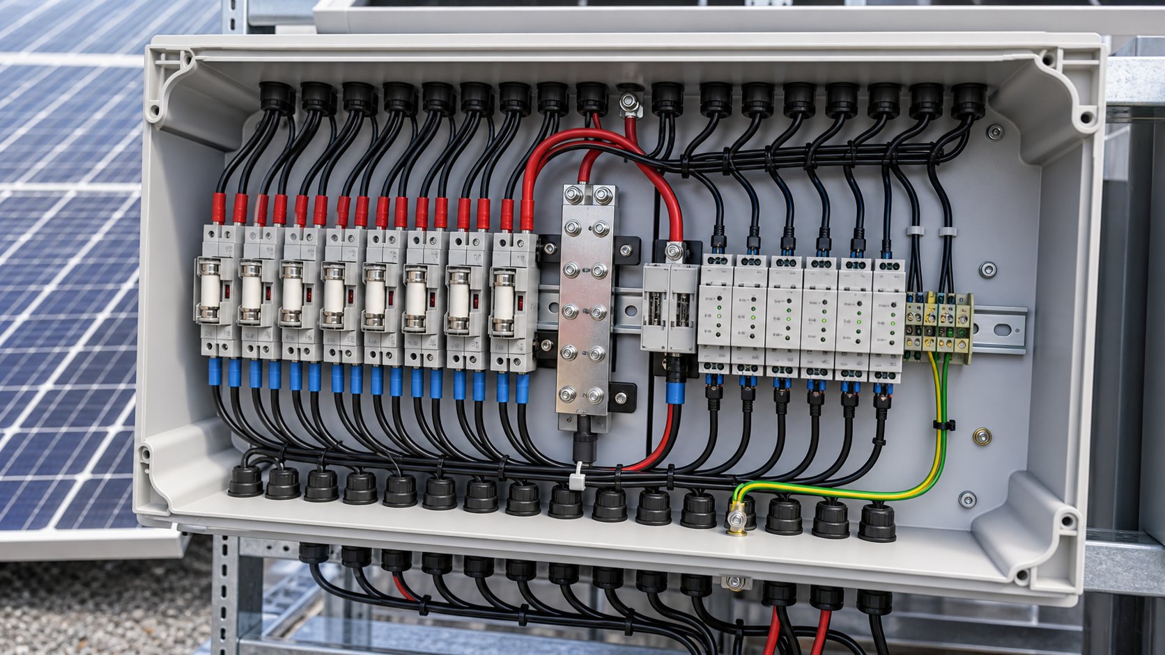
In a hybrid plant the combiner box remains the aggregation point for the PV strings. Its job is unchanged in principle and more demanding in practice:
The difference in a hybrid plant is coordination: the combiner box must be specified so its isolation, protection and monitoring boundaries line up with the storage control enclosure and the plant switchgear, not just the PV array in isolation.
- Collect multiple PV strings, each protected by its own gPV fuse and monitored at the output.
- Provide a DC isolation point so the array can be safely de-energized for maintenance alongside the storage side.
- Stage DC surge protection matched to the system voltage so transient events do not propagate toward the rest of the plant.
- Deliver a clean, protected DC bus to the downstream conversion stage, which is the adjacent system supplied by others.
3. Energy storage control equipment interface
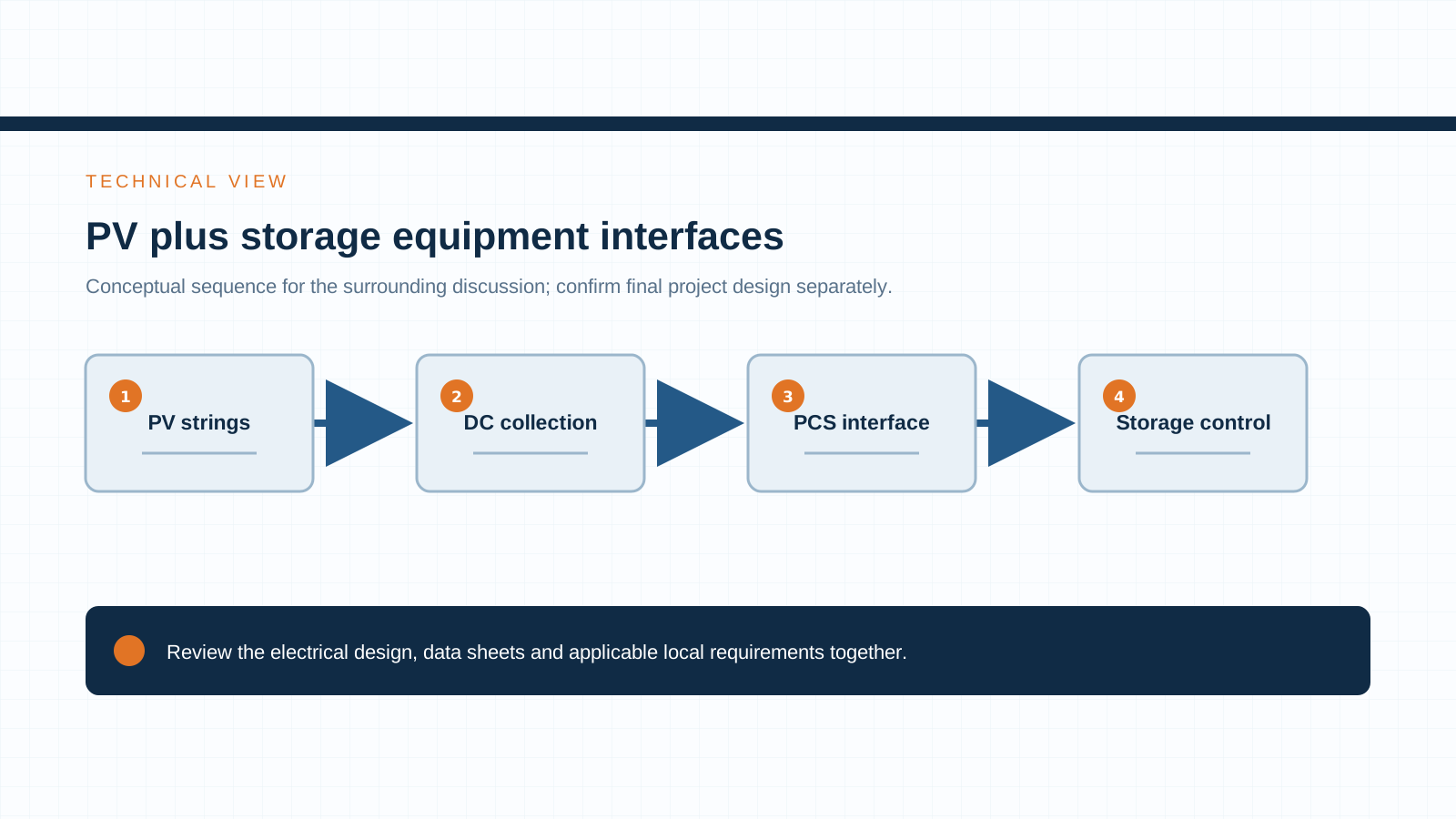
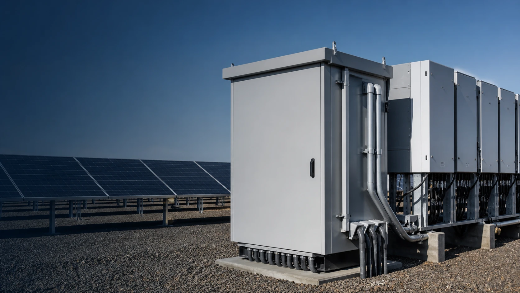
The energy-storage control enclosure is the NEUTRON-supplied interface that manages coordination signals and protection logic between the PV BOS and the storage stage. It is not the battery and not the inverter — those are the adjacent system supplied by others. Its role in the hybrid plant is to provide:
Placing a dedicated control enclosure between the collected PV DC bus and the storage stage keeps the coordination logic local, serviceable and independent of the battery or inverter vendor.
- A controlled isolation and switching point on the storage side of the DC bus.
- Protection and monitoring functions that can be coordinated with the PV combiner box protection.
- Control and signaling interfaces so the plant controller can manage PV and storage stages as one asset.
Technical diagram shown at a readable responsive scale.
4. DC protection and switchgear coordination
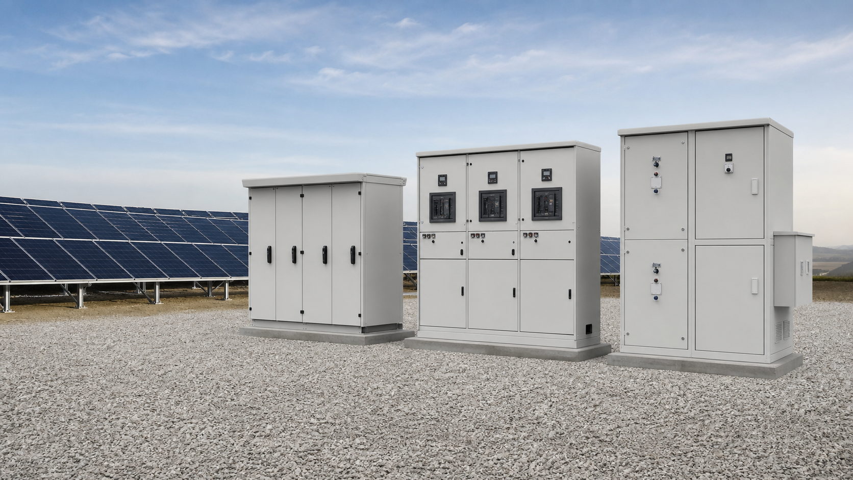
Coordination across the hybrid plant depends on three layers working together: the string-level DC protection inside the combiner box, the energy-storage control enclosure protection, and the low-voltage switchgear that ties the plant sections together. The objectives are selective tripping and a defined fault path:
Selective coordination means a fault on one string or one section opens only the device nearest that fault. Designing this requires matching breaking capacities, time–current behavior and isolation ratings across all three equipment types before the plant is built.
- gPV fuses in the combiner box clear a string fault without dropping the whole array.
- DC isolation and protection in the energy-storage control enclosure isolate the storage side cleanly.
- Low-voltage switchgear provides the main plant isolation and sectionalizing between PV and storage sections.
5. Isolation and protection between PV and storage sides
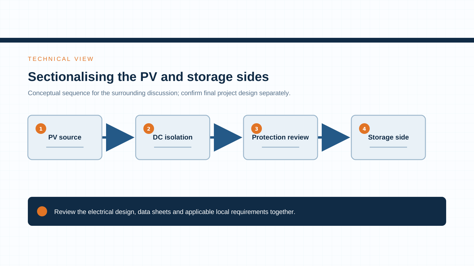
A defining feature of a hybrid plant is the need to isolate the PV and storage sides from each other without taking the whole plant down. This is achieved with independent, lockable isolation on each side:
Because the PV array behaves as a continuous DC supply whenever light is present, isolation on the PV side must be rated for DC breaking, not just AC duty. The same logic applies to the storage-side disconnect in the control enclosure.
- The combiner box DC disconnect isolates the PV array for string and box maintenance.
- The energy-storage control enclosure disconnect isolates the storage stage for service.
- Sectionalizing in the low-voltage switchgear lets one side be worked on while the other remains energized under controlled conditions.
Technical diagram shown at a readable responsive scale.
6. Standards that govern the design
A hybrid PV+storage BOS is governed by a stack of standards that touch each equipment type:
Specifying to these standards — and verifying them on each datasheet — is what keeps a hybrid plant serviceable and compliant as it scales.
- IEC 61439-8 — assemblies for use in photovoltaic installations.
- IEC 61439 — low-voltage switchgear and controlgear assemblies.
- IEC 62477 — safety of power electronic converter systems, relevant to the coordination of conversion and control equipment.
- Grid codes — local interconnection and grid-forming requirements that define how the storage stage must behave and therefore how the BOS must be coordinated.
7. Specification discussion: control and switchgear scope, not batteries or inverters
When issuing an enquiry for a hybrid PV+storage plant, keep the discussion scoped to the equipment NEUTRON provides and its coordination with the adjacent system supplied by others:
A clear specification conversation around these points — rather than mixing battery and inverter detail into the BOS scope — is what produces a coordinated, installable hybrid plant.
- Combiner box: number of strings, system DC voltage, gPV fuse rating and DC SPD staging.
- Energy-storage control enclosure: isolation rating, protection coordination and control interfaces to the plant controller.
- Low-voltage switchgear: sectionalizing scheme, breaking capacity and isolation between PV and storage sections.
- Boundaries: battery cells and inverters are the adjacent system supplied by others; the BOS discussion covers how NEUTRON equipment interfaces with them, not their internal design.
This is general technical guidance. Final ratings, standard editions, protection coordination and compliance evidence must be confirmed for the actual project and applicable local requirements.
Frequently asked questions
How does a combiner box coordinate with a storage plant?
The combiner box aggregates and protects the PV strings and provides a clean DC isolation point. Its protection and isolation boundaries are coordinated with the energy-storage control enclosure and the low-voltage switchgear so a fault on one side clears selectively without dropping the whole hybrid plant.
What does NEUTRON provide for PV+storage?
NEUTRON supplies the coordination equipment on the BOS side: PV combiner boxes, DC protection, low-voltage switchgear and energy-storage control enclosures. Battery cells and inverters are the adjacent system supplied by others; NEUTRON equipment provides the interface and protection around them.
Which standards apply to hybrid PV+storage BOS?
Key standards are IEC 61439-8 (PV combiner box assemblies), IEC 61439 (low-voltage switchgear assemblies), IEC 62477 (power electronic converter system safety) and the applicable local grid codes that define storage behavior and interconnection.
Do you need separate protection for PV and storage sides?
Yes. Each side has its own string or stage protection, its own lockable DC isolation, and they are sectionalized in the low-voltage switchgear. Independent protection lets one side be isolated and serviced without de-energizing the entire plant.
Bring the project inputs to the first review.
NEUTRON reviews the application context and prepares a configuration discussion around project requirements and the applicable document package.
Discuss a projectContinue learning
Explore related technical guidance in Solar PV.
Technical note: confirm the applicable standard edition, project design basis, local requirements and evidence package before final equipment selection or release.