
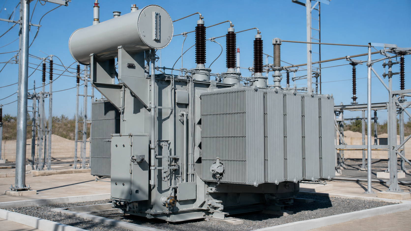
2. DGA: the fault gases and what they mean
Mineral insulating oil is a hydrocarbon. Apply enough energy and the molecular bonds break, releasing a specific mix of gases that depends on how much energy and in what form. Cellulose paper decomposes differently again, producing carbon oxides. Reading that mix is the whole basis of DGA under IEC 60599.
Table 1 — Principal dissolved gases and the fault conditions they indicate
Acetylene deserves special attention. It only forms at temperatures above roughly 700 C, which in a transformer means an arc. Any measurable acetylene in a unit that previously showed none warrants an immediate repeat sample and an engineering review before the unit is reloaded.
1. Why condition-based maintenance pays
A distribution or power transformer is usually the single most expensive item in a substation and the one with the longest replacement lead time. Windings, core and cellulose insulation are not repairable in the field. When the insulation system reaches end of life, the unit is replaced, and the outage is measured in weeks or months rather than hours.
That asymmetry is what justifies a testing programme. The cost of a quarterly oil sample and an annual full oil analysis is trivial against the cost of an unplanned failure, and the diagnostic lead time is genuinely useful: a developing thermal fault typically shows a rising gas trend for months before it becomes critical.
Three maintenance philosophies exist in practice. Reactive maintenance waits for failure and is only defensible for small, non-critical, easily replaced units. Time-based maintenance performs fixed tasks on a calendar and catches obvious problems but wastes effort on healthy assets. Condition-based maintenance uses measured indicators — dissolved gases, oil chemistry, thermal imaging, load history — to direct effort where it is needed. For any transformer above roughly 1 MVA or in a process-critical position, condition-based monitoring is the defensible choice.
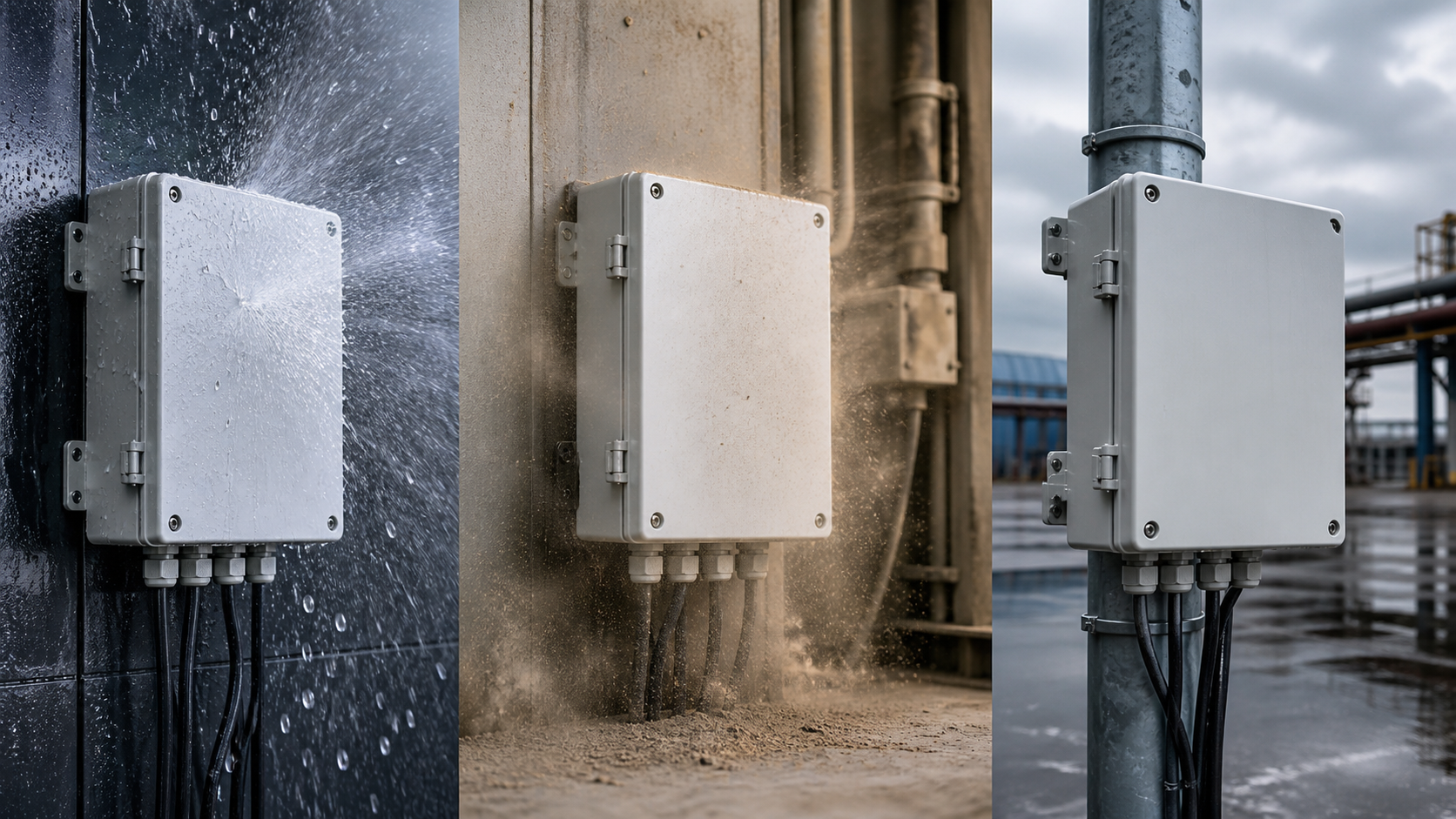
3. Interpreting DGA results: ratios and trends
A single gas concentration in parts per million tells you very little. Interpretation depends on two things: the ratio between gases, and the rate of change over time.
Establish a baseline for every transformer within the first year of service, and sample on a consistent schedule with consistent technique. Gas figures from different laboratories, different sampling points or different syringe handling are not comparable. Trend one asset against itself.
- Duval Triangle. Plots the relative proportions of methane, ethylene and acetylene on a triangular chart divided into fault zones — partial discharge, low and high thermal faults, and discharges of low and high energy. It is robust because it uses only ratios and therefore tolerates uncertainty about total gas volume.
- Rogers Ratio Method. Uses paired ratios such as C2H2/C2H4 and CH4/H2 to place the fault into coded categories. Reliable for classic fault types, less decisive on mixed or evolving faults.
- Key gas method. Identifies the single dominant gas and infers the fault type directly. Useful as a first sanity check.
- Rate of gas generation. Often more informative than any absolute value. A unit that has held 200 ppm of hydrogen for five years is behaving differently from one that reached 200 ppm in two months.
4. Oil quality beyond DGA
DGA finds active faults. Oil quality testing to IEC 60422 tells you whether the insulating medium itself is still doing its job. Four measurements carry most of the diagnostic weight.
Table 2 — Core oil quality indicators and typical in-service guidance
Acidity and IFT move in opposite directions as oil ages and are best read together. Oil that shows high acidity with low IFT is generating sludge, which blocks cooling ducts, raises hot-spot temperature and accelerates the whole degradation cycle. At that point the decision is between oil reclamation and a full oil change, and it should be made on measured numbers rather than on service hours.
5. Routine inspection and leak control
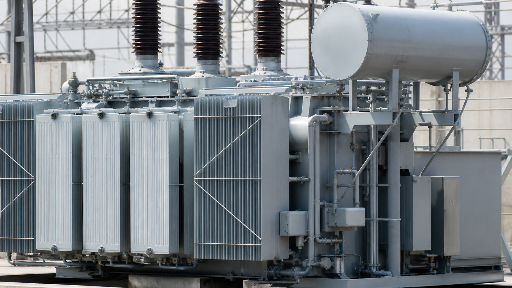
Oil loss is not just a housekeeping problem. A falling oil level exposes windings, and every leak path is equally a moisture and oxygen ingress path in the opposite direction when the unit cools and draws a partial vacuum.
Where leaks start, in rough order of frequency:
Fix leaks properly. A temporary epoxy patch on a live radiator is acceptable as a bridge to an outage, not as a repair. On every inspection also verify the silica gel breather colour, the Buchholz relay for accumulated gas, the oil temperature and winding temperature indicators, the pressure relief device, and the condition of the earthing connections. Thermal imaging of bushings, connections and the tank surface under load costs minutes and finds problems that no oil test will show.
- Gaskets and flange joints — compression set from thermal cycling is the normal ageing mechanism. Replace with the correct nitrile or fluoroelastomer profile, never with generic sheet material cut on site.
- Bushing seals — porcelain-to-flange joints suffer from differential expansion. Check for oil weeping around the lower petticoat.
- Radiator and cooler headers — vibration fatigue at weld toes and at pipe supports.
- Drain, sampling and filter valves — usually a worn valve stem packing rather than a body fault.
- Conservator and Buchholz pipework — small-bore connections that are easy to strain during other work.
6. A workable maintenance schedule
Intervals should be adjusted for criticality, load factor and ambient conditions, but the following framework is a defensible starting point for a distribution or medium power transformer in continuous service.
Table 3 — Baseline inspection and testing intervals
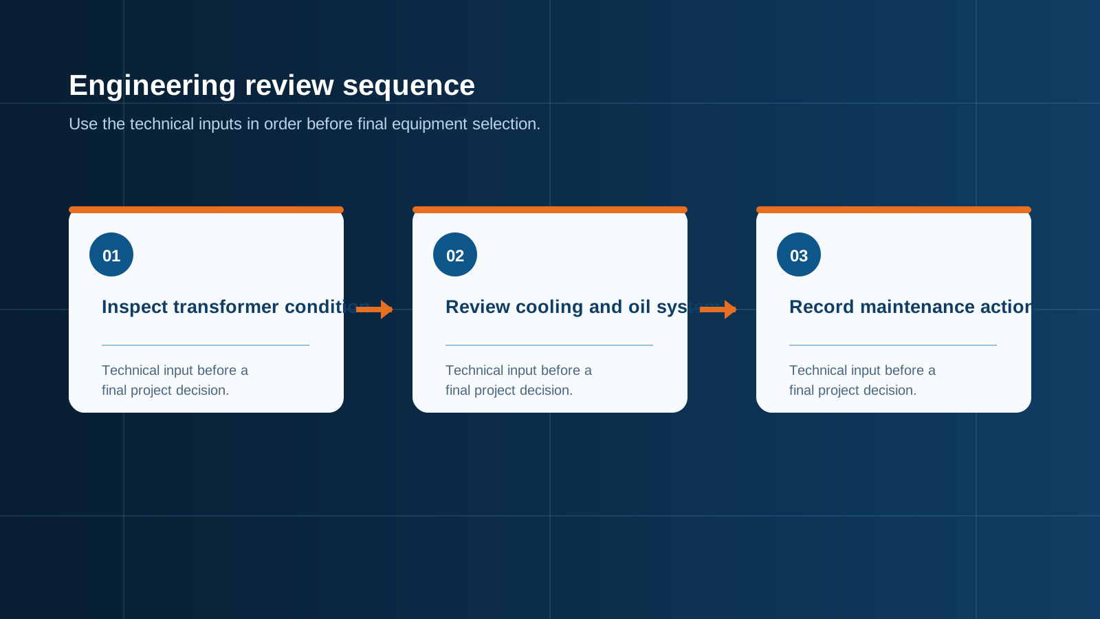
Technical diagram shown at a readable responsive scale.
7. Safety protocols that are not negotiable
Transformer maintenance combines stored electrical energy, hot oil, confined spaces and heavy lifting. The following rules are not optional and should appear in every written method statement.
Local qualification applies. National electrical safety rules, environmental regulations for oil handling and permit-to-work systems vary by market. Verify against the rules of the country of installation before adopting any procedure described here.
- Isolate, lock and tag on both HV and LV sides. A transformer back-feeds. Isolating only the primary leaves the unit energised from the secondary.
- Discharge and earth the windings. Capacitive charge remains after switching. Apply earths and leave them applied for the duration of the work.
- Prove dead at the point of work with an instrument that has been proved before and after.
- Treat the tank as a confined space for any internal work: gas test, forced ventilation, standby attendant, retrieval equipment.
- Manage hot oil. Oil above its flash point is a fire hazard and hot oil burns are severe. Allow cooling, use the correct decanting equipment, and have containment and absorbent in place before breaking any joint.
- Control the oil environmentally. Bunding, spill kits and a disposal route for used oil and oil-contaminated waste are part of the job plan, not an afterthought.
- Only competent personnel. DGA interpretation, tap changer work and internal inspection all require specific training and, in most jurisdictions, formal authorisation.
8. Procurement notes and where NEUTRON fits
Maintenance outcomes are shaped at procurement. A transformer installation that was specified without sampling valves, without accessible gauges or without adequate working clearance around the tank will be maintained badly for its entire life.
Specify these at order stage:
NEUTRON supplies the switching, protection and control equipment around the transformer: LV switchgear assemblies to IEC 61439, incomer and feeder cabinets, ATS and dual-supply panels, capacitor and power factor correction cabinets, and DC control panels for substation auxiliary supplies. Enclosures are built in cold-rolled or galvanised steel, powder coated to RAL 7035, with protection classes from IP30 through IP65 to suit indoor switchrooms or outdoor compact substation housings. All assemblies are produced under an ISO 9001 quality system with CE and CB documentation available for export projects.
- Oil sampling valve at the correct height with a dedicated sampling point, so DGA samples are repeatable.
- Full instrumentation: oil temperature indicator, winding temperature indicator, oil level gauge, pressure relief device, Buchholz relay with alarm and trip contacts.
- Remote signalling of all alarm contacts into the plant monitoring system.
- Physical access: working clearance around the tank for radiator inspection and for thermal imaging sight lines.
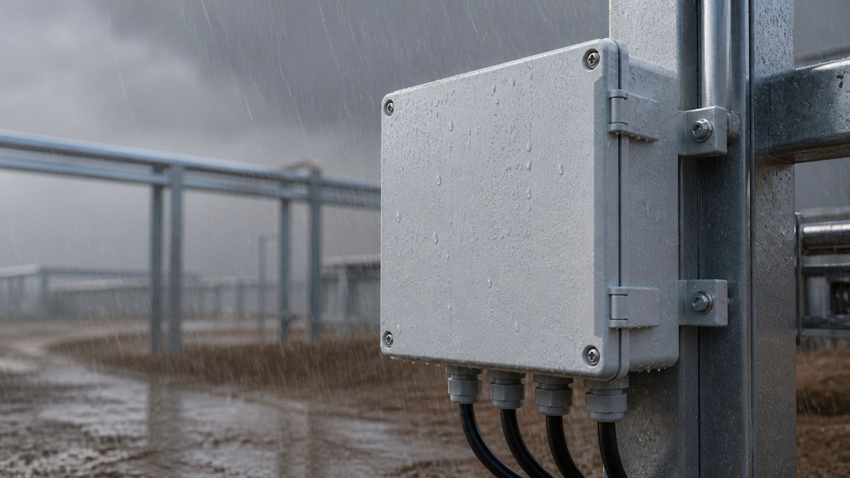
- Documentation: factory test certificates, oil certificate with baseline DGA, and a rated diagram plate that survives outdoor exposure.
This is general technical guidance, not a substitute for local electrical code, the applicable standard, product datasheets or a qualified engineer's design review. Confirm ratings and final configurations against the actual project.
Bring the project inputs to the first review.
NEUTRON can review the application context, electrical envelope, enclosure conditions and document requirements related to the ultimate oil-filled transformer maintenance guide: dga and safety before quotation.
Discuss a technical requirementContinue learning
Explore related technical guidance in Power Distribution.
Converted from the approved Period 01 source article for The Ultimate Oil-Filled Transformer Maintenance Guide: DGA and Safety. Editorial instructions, duplicate anchor placeholders and embedded publishing directions were removed; the technical body is retained for educational use.