

Start with the current IEC 62548-1 scope
The current consolidated publication is IEC 62548-1:2023 together with Amendment 1:2025. It sets design requirements for all parts of the PV array and the final power-conversion equipment (PCE). It excludes energy-storage devices, loads and AC/DC distribution networks that supply loads, while also including additional protection requirements for PV arrays directly connected to batteries at DC level.
That boundary matters when a project combines PV generation, batteries, an inverter, backup loads and a site distribution system. Do not assume that one array-design standard governs every component or operating mode in the integrated plant. Map which equipment falls within the PV-array and final-PCE scope, then identify the separate requirements for storage equipment, loads and downstream distribution.
The standard provides design requirements for the array; individual fuses, breakers, switches and RCDs remain subject to their own product standards and declarations. A design reference does not qualify a particular device, establish its interrupting capability or prove that the assembled installation meets every local rule.
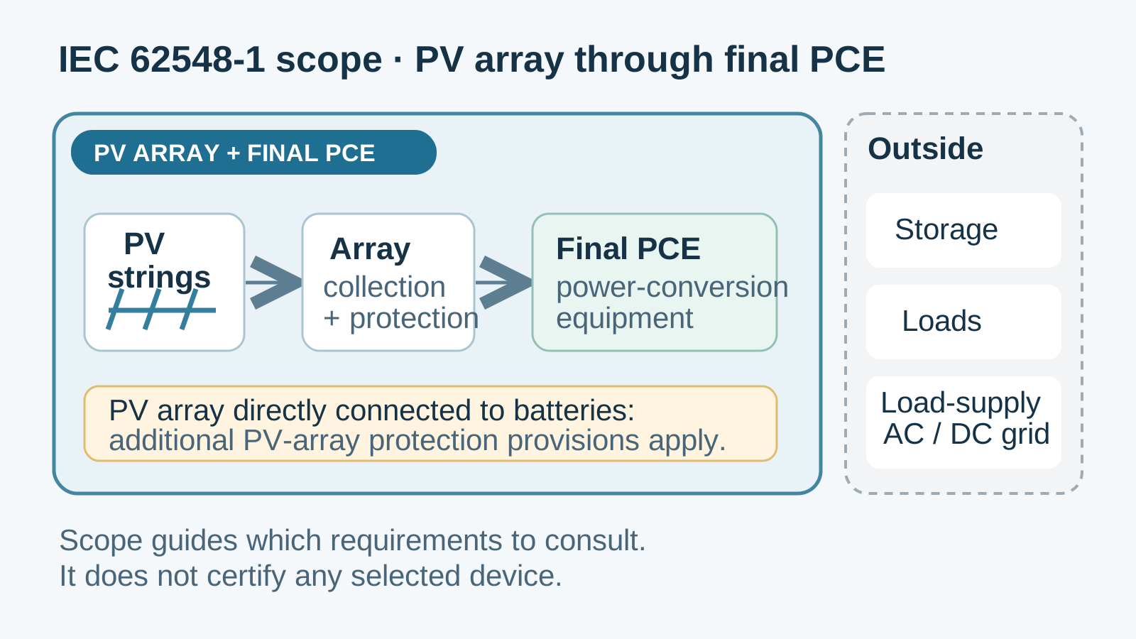
Technical diagram shown at a readable responsive scale.
Map every protective function to its circuit
Begin with the system single-line diagram and identify the function of each device: string overcurrent protection, array or sub-array switching, collection-circuit protection, inverter input protection, AC feeder protection and any residual-current function. The exact arrangement depends on the array topology, earthing method, number of parallel circuits, equipment instructions and the adopted installation rules.
A device should not be credited with a function it is not rated or installed to perform. For example, a disconnecting function and an overcurrent-protection function may be provided by one product only if its declared ratings, construction and the applicable rules permit that use. Record the distinction in the schedule so a reviewer can see what each device is expected to do.
This functional map is more reliable than assuming a fixed hierarchy. It reveals missing coverage, overlapping devices and unclear boundaries before equipment is procured. It also helps the commissioning team test the correct function at the correct point without treating a component label as evidence of system-level coordination.
Base device ratings on project data
Compile the array’s maximum design voltage and current using the project’s environmental assumptions, module data and applicable calculation rules. Record the PV topology, parallel paths, conductor sizes, equipment limits and prospective fault conditions at each device location. Those inputs—not a generic example value—form the basis for comparing a product’s voltage, current and interrupting ratings.
Read DC device ratings at the stated voltage and connection configuration, and verify that the actual installation follows the manufacturer’s pole and wiring diagram. For AC equipment, use the inverter output data and the relevant feeder design. If a rating is close to a limit or depends on a special connection, make that dependency explicit in the calculation and drawing.
Coordination and selectivity still need proof
A citation to IEC 62548-1 does not by itself demonstrate that a set of series devices will operate selectively. Selectivity depends on device characteristics, available fault current, voltage, conductor arrangement and the manufacturer’s coordination data. In PV circuits, source behaviour and parallel paths can affect the fault conditions, so the design must use project-specific information rather than assume that ordinary AC time grading applies unchanged.
For each relevant fault scenario, state which protective element is intended to operate and what evidence supports that choice. Where the manufacturer provides selectivity, backup-protection or cascading tables, confirm that the exact product references and conditions match the project. If data are absent, describe the limitation and obtain an engineering assessment rather than promising discrimination.
Review residual-current protection at the conversion interface
Residual-current protection on an inverter’s AC side requires a separate review of the device function, possible residual-current waveform, inverter design and manufacturer instructions. The correct detection class is not universal across all PV systems. Check whether the inverter has relevant monitoring or disconnection functions and whether the installation rules require an external device at that position.
When a particular class is specified, verify that the selected RCD’s product evidence supports it and that the exact model is used within its declared conditions. Keep this decision separate from the array’s DC overcurrent-protection schedule: the devices address different hazards and must be coordinated across the conversion boundary without conflating their standards.
Build a coordination record that can be reviewed
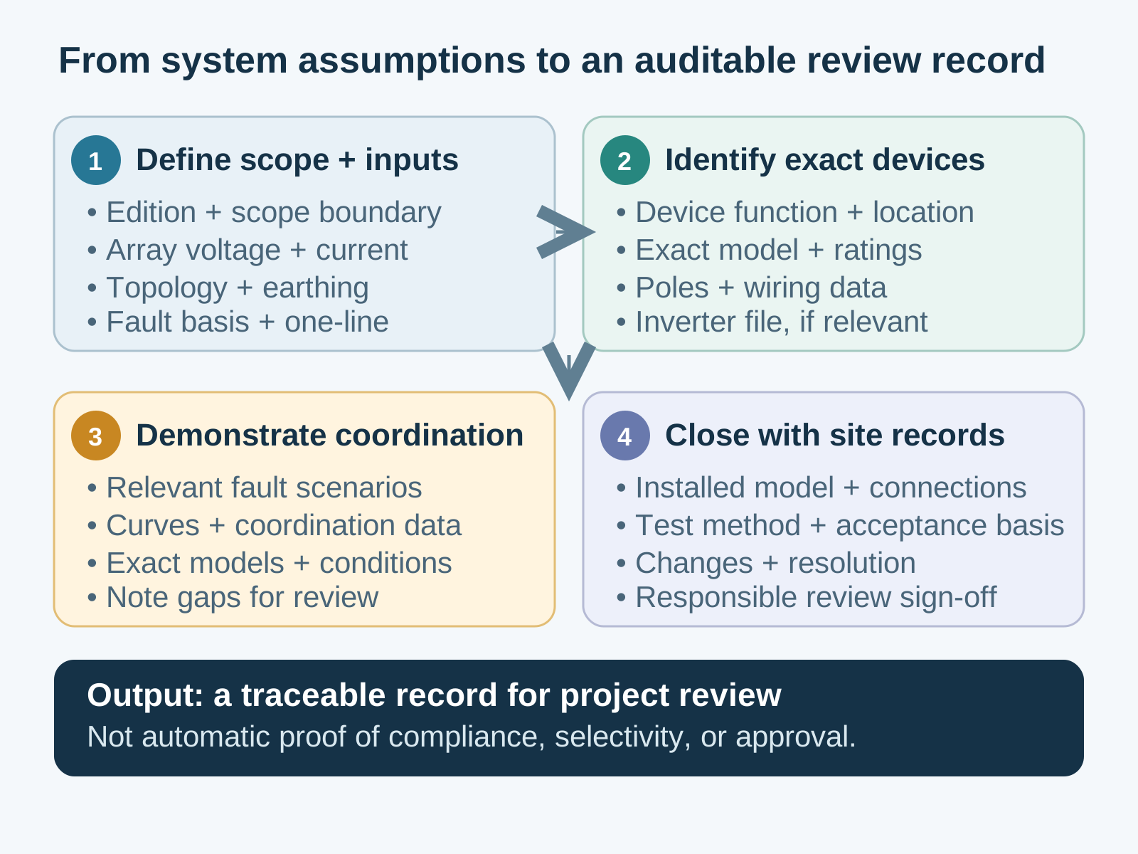
A useful project package includes the standard edition and scope assumptions; array voltage and current calculations; environmental conditions used; a current single-line diagram; device schedule with exact model and ratings; manufacturer connection diagrams; fault-current or coordination calculations where required; earthing and fault-detection description; inverter manuals; and the local code or contract requirements used for acceptance.
These records help an engineer, owner or authority understand how the design was developed, but they are not a universal checklist of documents required by every jurisdiction. Tailor the package to the project and label items as design evidence, manufacturer evidence or commissioning records. That distinction avoids presenting a recommended review file as a legal mandate.
Close the loop during installation and commissioning
During installation, compare the fitted device references, ratings and connections with the approved schedule and drawings. Record departures and resolve them before energization. Commissioning tests should follow the applicable rules and equipment instructions, with the test method and acceptance criterion identified in the record.
A completed checklist is valuable only when it ties measured or inspected results to the design assumptions. If the measured site condition differs materially from the input used for sizing or coordination, return the design for review. Do not treat the presence of each listed component as proof that the complete protection scheme is coordinated.
A practical sequence for the design review
First, confirm the applicable edition and scope boundary. Second, identify the PV array circuits and the PCE interface. Third, assign each protective and switching function to a device location. Fourth, compare project design values with each exact product rating and connection diagram. Fifth, check coordination data and any inverter protective functions. Finally, document the code basis, commissioning method and unresolved assumptions for responsible engineering approval.
This avoids an outdated standard citation and the assumption that citing a standard proves selectivity. It gives procurement a clear evidence request and reviewers a traceable route from system data to the installed device.
General technical guidance only. Confirm the current consolidated standard, applicable local rules, product ratings, manufacturer instructions and project calculations with the responsible electrical engineer.
Frequently asked questions
Which IEC 62548 edition should a current project check?
The official IEC catalogue identifies the consolidated publication IEC 62548-1:2023 together with Amendment 1:2025. Confirm the edition required by the project specification and jurisdiction, then use its published scope rather than an older shorthand citation.
Does IEC 62548-1 cover batteries and downstream loads?
Its scope includes all parts of the PV array and final PCE, while excluding energy-storage devices, loads and AC/DC distribution networks that supply loads. It also includes additional protection requirements for PV arrays directly connected to batteries at DC level; the battery equipment itself remains outside the scope.
Does citing IEC 62548-1 prove that breaker selectivity is achieved?
No. Selectivity depends on the actual devices, fault conditions, system arrangement and manufacturer coordination data. The designer must demonstrate the intended operating sequence for relevant fault scenarios using project-specific inputs; the array-design standard citation alone is not proof.
Does every transformerless PV inverter require a Type B RCD?
No universal requirement should be inferred from that description alone. Check the exact inverter documentation, built-in monitoring, circuit function and applicable installation rules. The responsible engineer should select and document the detection class for the project’s actual conditions.
Trace each rating back to the system design
A clear single-line diagram, project-specific calculations and exact product records make the protection review reproducible from design through commissioning.
Discuss a project requirementContinue learning
Explore related technical guidance in Electrical Protection.

The current IEC 62548-1 consolidated publication and its stated scope are linked in the opening section. Product standards, local code requirements and coordination data must be reviewed separately.