

What IEC 61008 and IEC 61009 cover
IEC 61008-1 addresses residual-current operated circuit-breakers without integral overcurrent protection, commonly called RCCBs. IEC 61009-1 addresses residual-current operated circuit-breakers with integral overcurrent protection, commonly called RCBOs. The 2024 editions cover household and similar use up to 440 V AC and 125 A; IEC 61009-1 also states a maximum rated short-circuit capacity of 25 kA. These are scope limits, not blanket evidence for industrial PV assemblies.
The distinction matters when preparing a device schedule. An RCCB detects residual current and opens its circuit, but a separate device must provide the required overload and short-circuit protection. An RCBO combines residual-current and overcurrent functions in one device. That describes their functional construction; it does not by itself decide which arrangement is appropriate for a particular PV feeder, board or jurisdiction.
Check the intended application, voltage and current, fault conditions and product category. If the installation is outside the published scope, identify the applicable product and assembly standards rather than stretching a household/similar-use designation.
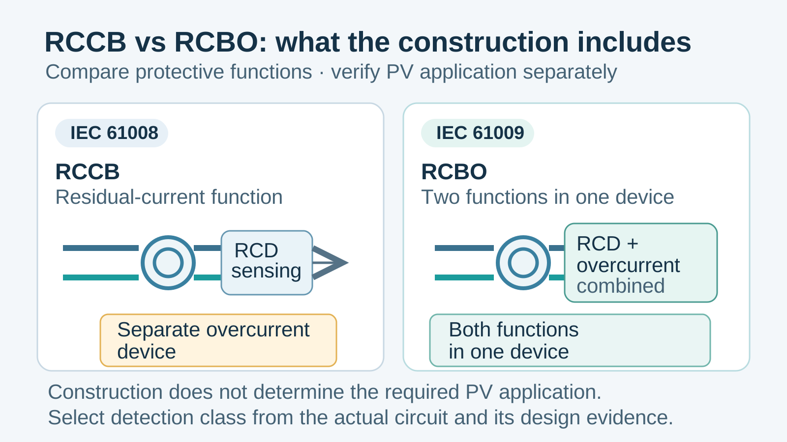
Technical diagram shown at a readable responsive scale.
RCCB or RCBO: match construction to the board
An RCCB may be used where residual-current protection is provided as a group function and separate overcurrent devices protect the outgoing circuits. The designer must account for the RCCB’s declared short-circuit coordination conditions and for the consequences of one residual-current event disconnecting multiple circuits. An RCBO can provide an individual residual-current and overcurrent function per circuit, but the device still has to match that circuit’s ratings and coordination requirements.
Neither arrangement is automatically safer or more compliant in every layout. The useful comparison is operational: which conductors and loads are protected, what else disconnects after a fault, how are upstream and downstream devices coordinated, and can maintenance staff identify the affected circuit? Record those choices on the single-line diagram and circuit schedule instead of inferring them from the product name.
Treat detection class as a separate decision
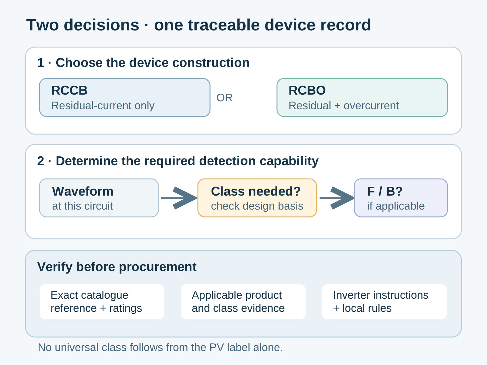
The base construction standard and the residual-current waveform class answer different questions. IEC 62423 adds requirements for Type F and Type B RCDs used with the relevant IEC 61008 or IEC 61009 constructions. A stated Type F or Type B capability should therefore be checked against the product documentation and the appropriate supplementary standard, not inferred from the device being called an RCCB or RCBO.
A PV inverter does not make Type B a universal requirement. The selection depends on the residual-current waveforms that can occur, the inverter’s instructions and built-in monitoring or disconnection measures, the protective function required at that location, and the rules adopted for the project. Where the design uses a class other than Type B, the rationale should be traceable to the actual equipment documentation and applicable installation requirements.
Do not turn a general description such as ‘transformerless inverter’ into an automatic device prescription. Different inverter designs and installation rules can impose different conditions. Confirm the manufacturer’s exact statement for the model and operating mode, then have the responsible electrical designer determine whether an external RCD is required and what class it must provide.
Verify evidence for the exact catalogue reference
For procurement, compare the model on the offer, device marking, datasheet and certification record character by character. Confirm the number of poles, rated current, rated residual operating current, voltage, short-circuit coordination or breaking data, and any detection-class marking relied on in the design. A family-level document is useful only if its scope explicitly includes the supplied reference and configuration.
Request the applicable product-standard evidence and any supplementary detection-class evidence as separate items when the claim depends on both. Also record the manufacturer’s declaration and installation instructions. A sales description that says ‘PV suitable’ is not a substitute for a model-specific rating or a clear statement of the conditions under which the device may be used.
Understand what a test button does—and does not establish
Use the integral test control only as directed by the product manufacturer. It is a functional check of the device’s test arrangement; it should not be treated as a substitute for an instrument-based trip-time or sensitivity test where commissioning rules require one. Nor should a test-button result be interpreted as proof that every waveform or frequency relevant to a PV application has been evaluated.
A commissioning record should identify the installed model and settings, test instrument and method, measured results, and the acceptance criteria taken from the applicable rules and device documentation. This keeps measured performance separate from assumptions based on a front-panel button or a generic expected value.
Coordinate inverter functions with board protection
An inverter may include residual-current monitoring, insulation monitoring or other protective functions. Their presence does not automatically show that they replace an external device required to protect a feeder, downstream wiring or another part of the assembly. Read the inverter manual and conformity documents to identify the function, monitored conductors, trip conditions and the boundary of protection.
Assign each fault condition to a protective function and location. Check the disconnection sequence and upstream RCD rather than assuming selectivity. Resolve unclear protection boundaries with the inverter manufacturer and responsible engineer before installation.
A practical RCD specification checklist
Before approving a device, document its circuit location and function; the product standard and edition; rated voltage and current; residual operating characteristics; required detection class and its supporting standard; short-circuit coordination conditions; pole and wiring arrangement; and the exact model covered by the submitted evidence. Add the inverter reference, relevant manual revision and the local installation rule used to reach the detection-class decision.
This checklist does not certify a design by itself. It makes the assumptions reviewable and gives the installer, inspector and future maintenance team a common record. Where the site or equipment falls outside the product standard’s scope, state the alternative assessment route and its acceptance basis instead of silently treating a familiar label as proof.
General technical information only. Device selection and installation must be checked against the exact product documentation, inverter instructions, applicable local rules and review by the responsible electrical engineer.
Frequently asked questions
How do IEC 61008 RCCBs differ from IEC 61009 RCBOs?
An IEC 61008 RCCB provides residual-current protection without integral overcurrent protection, so the circuit needs separate overload and short-circuit protection. An IEC 61009 RCBO combines residual-current and overcurrent functions. Check each standard’s scope and the exact device ratings before applying either construction to a PV circuit.
Does every transformerless PV inverter require a Type B RCD?
No universal rule follows from the inverter topology alone. Check the exact inverter manual and built-in residual-current measures, the protection function required at that circuit, the applicable installation rules and the project design. Use Type B only where those conditions and the product evidence call for it.
What does IEC 62423 add to an RCD specification?
IEC 62423 provides supplementary requirements for Type F and Type B devices used with the applicable IEC 61008 or IEC 61009 construction. It does not replace the base construction standard, and a claimed class should be supported for the exact device reference being supplied.
Is pressing the test button enough for commissioning?
Not where the commissioning procedure requires measured trip time or sensitivity results. Follow the device instructions and applicable test rules; record the instrument, method and measured result. The test button alone should not be treated as evidence for every waveform or frequency relevant to the installation.
Make the selection auditable
Record the device function, exact model, inverter evidence and applicable installation rule together so the protection decision can be reviewed and maintained.
Discuss a project requirementContinue learning
Explore related technical guidance in Electrical Protection.

Standard scopes and device-selection caveats were checked against the official IEC publication pages listed in the relevant sections. Project-specific rules and product declarations still require separate verification.