
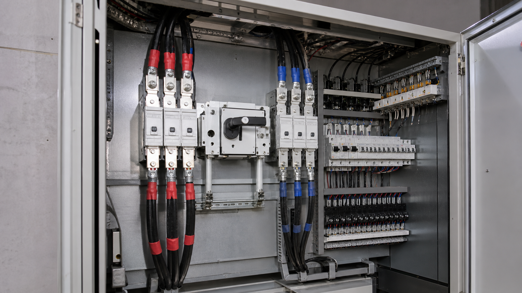
2. The 6 mA rule in IEC 61851-1
IEC 61851-1, the standard for conductive charging of electric vehicles, sets the threshold explicitly. Every AC charging point must provide protection that disconnects the supply when the smooth DC residual current exceeds 6 mA.
Six milliamps is not an arbitrary figure. It is the level at which DC current begins to interfere with the correct operation of conventional residual current devices, and it sits below the threshold at which DC leakage becomes physiologically hazardous. Two compliant implementations exist:
The second route is common in factory-built charging posts because the manufacturer can integrate the 6 mA sensor cheaply. It is only valid if the charger datasheet explicitly declares the RDC-DD function. Never assume it is present — many lower-cost units simply are not equipped, and installing them behind a plain Type A device leaves the installation non-compliant.
- A Type B residual current device to IEC 62423, installed in the distribution board feeding the charging point. It detects AC, pulsating DC and smooth DC residual currents in one device.
- A Type A residual current device to IEC 61008-1 or IEC 61009-1, combined with a residual direct current detecting device (RDC-DD) to IEC 62955 that is built into the charging equipment.
1. Where DC residual current comes from in EV charging
In AC charging, the on-board charger inside the vehicle converts grid AC into the DC the battery needs. It does this with a rectifier stage, a DC link and a high-frequency switching converter. In DC charging, the same conversion happens inside the charging post itself.
Either way, a substantial DC potential exists inside the equipment, separated from earth only by insulation, filter capacitors and creepage distances. Insulation degradation, moisture ingress into a connector, a damaged cable or simply the leakage through Y-capacitors in the electromagnetic compatibility filter can allow a small DC current to flow to earth.
That current is not a theoretical concern. Charging equipment lives outdoors, gets driven over, is plugged and unplugged thousands of times, and operates at high power for hours. It is one of the few loads in a building where a persistent, converter-derived earth leakage path is genuinely likely.
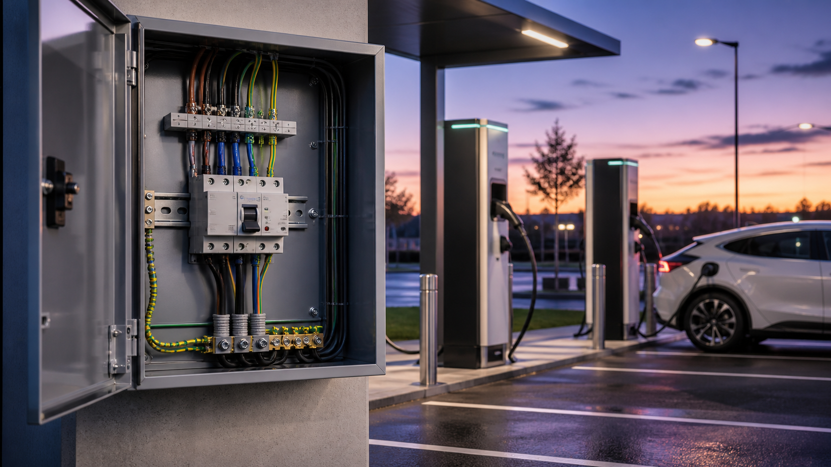
3. Core saturation: why a Type A device can miss the fault
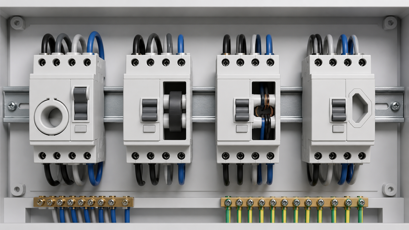
A residual current device works by summing the currents in all live conductors through a toroidal core. If the vector sum is not zero, the difference produces an alternating flux in the core, which induces a voltage in the detection winding and trips the mechanism. The whole principle depends on flux that changes.
A smooth DC residual current produces a constant flux instead. The detection winding sees nothing, so the device does not trip on the DC fault itself. That alone would be a limitation rather than a hazard.
The real problem is what the constant flux does to the core. It biases the operating point toward magnetic saturation, leaving far less usable flux swing for a genuine AC fault. The device is still fitted, its test button still works, and its indicator still shows healthy — but its actual AC sensitivity may have shifted well above its nameplate rating. This is the blinding effect, and it is why the standards treat DC leakage as a systemic risk rather than a niche one.
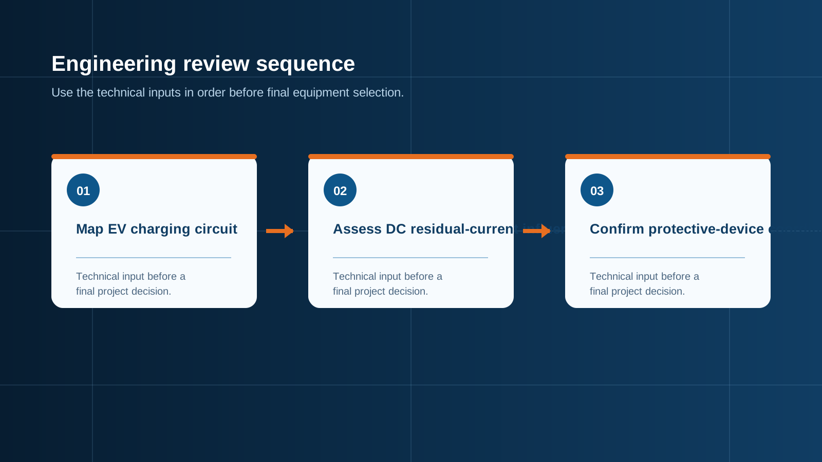
Technical diagram shown at a readable responsive scale.
4. The RCD type hierarchy: AC, A, F and B
IEC 61008-1 and IEC 61009-1 define the base device, and IEC 62423 defines the Type F and Type B requirements. Each type is a superset of the one before it.
- Type AC — detects sinusoidal AC residual current only. Adequate for resistive loads such as heaters and incandescent lighting. Not permitted for EV charging, and no longer permitted for general use in several national codes.
- Type A — adds pulsating DC residual current, which covers single-phase rectified loads. This is the current baseline for domestic and commercial final circuits.
- Type F — adds composite residual currents up to 1 kHz and tolerates a superimposed smooth DC component of up to 10 mA. Designed for single-phase inverter-driven loads such as washing machines and heat pumps. Not sufficient on its own for EV charging.
- Type B — adds smooth DC residual current detection and covers residual currents up to 1 kHz. Type B+ extends the frequency range to 20 kHz with a lower let-through curve, which is specified where fire protection is a stated design objective.
5. Detailed comparison table
Table — Residual current device types against EV charging requirements
6. Choosing between a Type B device and an RDC-DD charger
Both routes satisfy IEC 61851-1, so the decision is practical rather than regulatory.
- Choose a Type B residual current device in the board when the site has mixed charger brands, when chargers will be replaced during the life of the installation, when the client wants protection that is independent of the charging hardware, or when a single fault current path serves several outlets.
- Choose a Type A device plus an integrated RDC-DD when the charger is factory declared to IEC 62955, when board space is tight, and when the capital cost difference across many outlets matters. Record the declaration in the handover documentation.
- Never mix the assumptions. A charger with an integrated RDC-DD behind a Type B device is harmless but wasteful; a charger without one behind a Type A device is a compliance failure that will be found at inspection.
- For three-phase 22 kW charging, four-pole Type B devices are the normal answer, since the DC component can appear on any phase.
7. Designing the charging distribution board
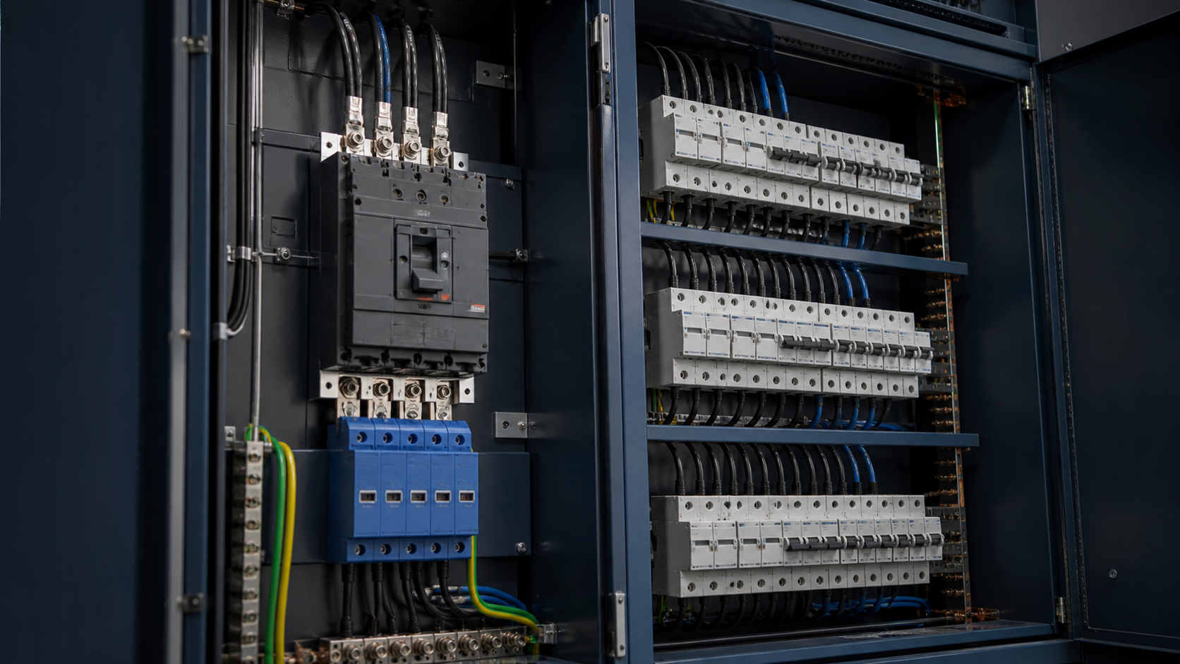
The protection device is one element inside an assembly that also has to survive an outdoor car park. NEUTRON manufactures the distribution equipment behind charging infrastructure — XL-21 power distribution cabinets, GGD and GCS low-voltage switchgear, feeder and metering cabinets, and outdoor enclosures — all built and verified to IEC 61439-1 and IEC 61439-2 with CE, CB and ISO 9001 documentation. Protection positions are populated to the project specification, including four-pole Type B positions where the design calls for them.
- One dedicated residual current device per charging point. Shared protection means one vehicle fault takes the whole car park offline.
- Enclosure protection IP54 to IP65 for outdoor installations, cold-rolled, galvanised or stainless steel with electrostatic powder coating in RAL 7035.
- Overcurrent protection sized for continuous duty: charging is a sustained 100% load for hours, not an intermittent one.
- Coordinated surge protection. NEUTRON WCU8 modular devices provide Type 2 protection with a response time below 25 ns, an operating range of −40 °C to +85 °C, thermal disconnection with green and red status indication, and an optional remote signalling contact rated AC 36 V 1 A.
- For larger installations, NEUTRON WCM30L moulded case residual current breakers cover 100 A, 225 A, 400 A and 800 A frames with adjustable residual settings from 30 mA to 500 mA and adjustable delay steps of 0.2 s, 0.4 s and 0.8 s to IEC 60947-2 — the practical way to build selectivity above the final circuits.
- Remote monitoring via RS485 or Modbus RTU so an operator sees a tripped charger without driving to the site.
8. Commissioning, testing and handover
- Test the residual current device with a tester capable of the correct waveform. A standard AC-only tester will not verify the DC detection function of a Type B device.
- Record trip times at IΔn, 2 IΔn and 5 IΔn, and record the measured earth loop impedance.
- Press the test button on every device at handover and record the result — it verifies the mechanism, not the sensitivity.
- Where an RDC-DD is relied upon, file the charger declaration of conformity to IEC 62955 with the electrical certificate.
- Schedule periodic testing. Outdoor charging equipment ages faster than indoor distribution, and a quarterly functional test is a reasonable baseline.
- Label the board clearly so a future contractor does not swap a Type B device for a cheaper Type A during maintenance.
Request a quote
NEUTRON manufactures the low-voltage distribution equipment behind electric vehicle charging infrastructure — outdoor distribution cabinets, XL-21 power distribution cabinets, GGD and GCS switchgear, WCM30L residual current breakers up to 800 A and WCU8 surge protection — all verified to IEC 61439 with CE, CB and ISO 9001 documentation. Send us the charger specification, number of bays and site conditions, and our engineers will return a board layout with drawings and device schedule.
This is general technical guidance, not a substitute for local electrical code, the applicable standard, product datasheets or a qualified engineer's design review. Confirm ratings and final configurations against the actual project.
Bring the project inputs to the first review.
NEUTRON can review the application context, electrical envelope, enclosure conditions and document requirements related to ev charging safety: the critical role of type b rccbs before quotation.
Discuss a technical requirementContinue learning
Explore related technical guidance in Electrical Protection.

Converted from the approved Period 01 source article for EV Charging Safety: The Critical Role of Type B RCCBs. Editorial instructions, duplicate anchor placeholders and embedded publishing directions were removed; the technical body is retained for educational use.