
2. Manual changeover switches
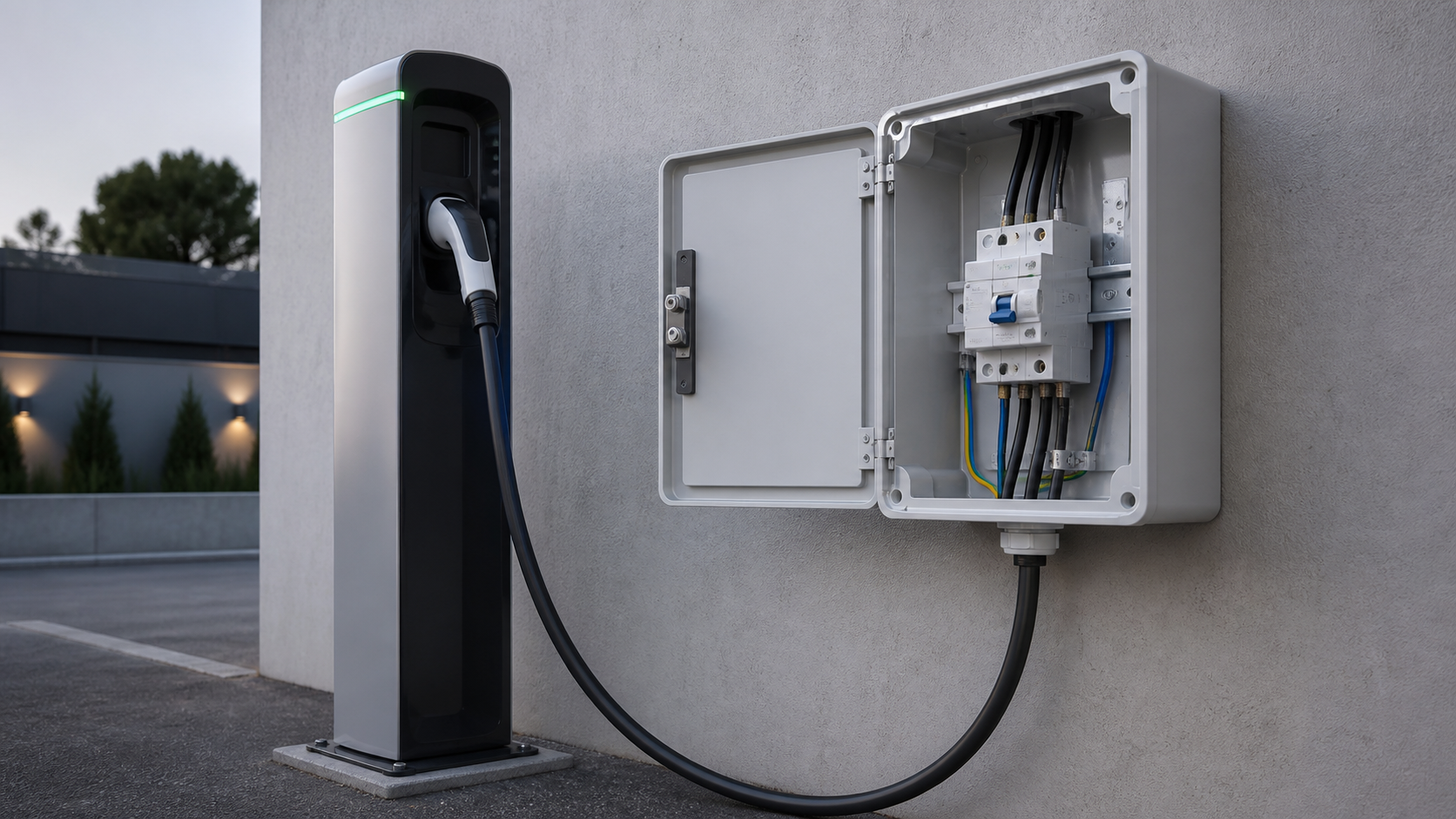
A manual transfer switch (MTS) is operated by a handle: an operator moves the switch from position I to position II. There is no sensing, no logic and no automatic action.
Where they fit:
Advantages: lowest capital cost, no control power, no electronics to fail, mechanically simple enough to stay serviceable for decades. Limitations: transfer depends on a person being present and competent. For process-critical or unmanned sites, a manual switch is not viable.
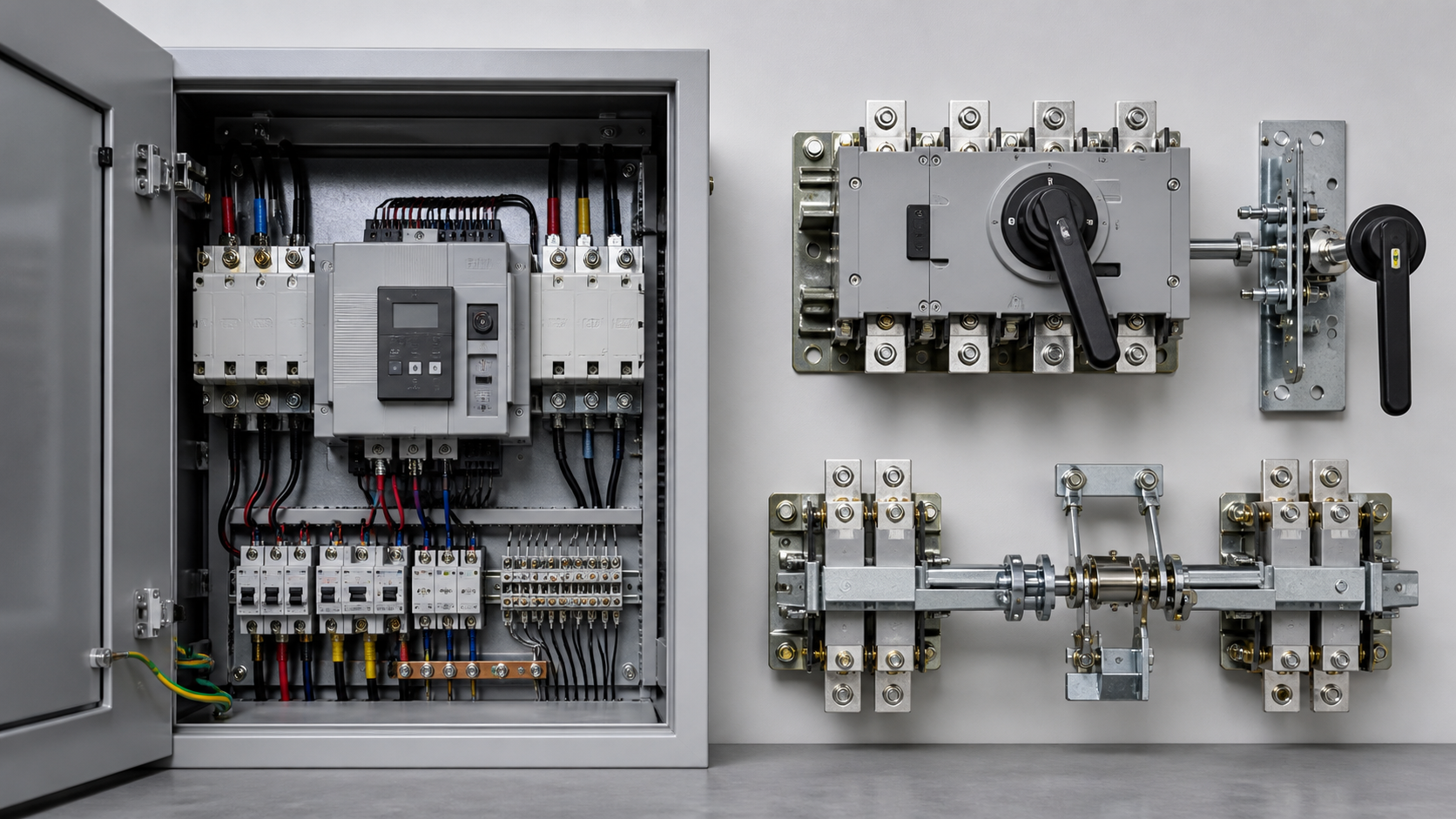
Manual devices are built from a rotary cam switch, a pair of mechanically interlocked moulded case breakers, or a purpose-built double-throw switch. Where interlocked breakers are used, verify the interlock is a factory mechanical assembly rather than an improvised bracket, and that both breakers share frame rating and breaking capacity.
- Small commercial premises where an outage of several minutes is acceptable.
- Portable generator connections at agricultural and construction sites.
- Maintenance bypass duty, allowing an automatic device to be worked on without dropping the load.
- Installations where the standby generator is started manually anyway.
1. What a changeover switch actually does
A changeover switch connects one load to either of two incoming supplies, and — critically — makes it physically impossible to connect both at once. That interlock is the entire safety justification for the device. Without it, a standby generator can back-feed onto a utility network that maintenance crews believe is dead.
Three requirements define a properly engineered changeover device:
Everything else — controllers, displays, communications, timers — sits on top of those three fundamentals.
- Positive interlocking. Both mechanical and electrical. NEUTRON WCQ2 devices carry both, so simultaneous closing of the two incomers cannot occur even if the control logic misbehaves.
- Defined transfer sequence. The load must be disconnected from the first incomer before it is connected to the second, with a deliberate both-open interval where motor loads are involved.
- Adequate switching duty. The contacts must make and break the actual load current repeatedly across the design life of the installation.
3. Motorised changeover switches
A motorised changeover switch is a manual switch fitted with a motor operator. The motor drives the mechanism on command from a remote contact, a control system or an operator's pushbutton, but the switch itself contains no supply-monitoring logic.
This is the middle tier, and it is frequently the right answer for installations that need remote operation but not autonomous decision-making:
Motorised switches usually retain a manual handle for emergency use. Confirm this, and that manual operation does not damage the motor drive — a sound design decouples the handle from the gearbox.
- Transfer initiated by a building management system that already monitors supply quality centrally.
- Installations where an operator must authorise the transfer for procedural reasons, but the switch itself is in an inaccessible or hazardous position.
- Load-shedding schemes where transfer is one action in a larger sequence controlled elsewhere.
4. Automatic transfer switches
An automatic transfer switch adds supply monitoring and decision logic. It watches voltage, frequency and phase status on the normal incomer, decides when the supply is unacceptable, signals the generator to start, transfers, and later returns the load when the normal incomer is stable again.
Two architectures are common, and NEUTRON manufactures both.
For small loads the compact WCQ2C-63 covers 10-63 A at 400 V, 50 or 60 Hz, with transfer in 3 seconds or less, control voltage AC 230 V, and an EPS fire interface accepting a DC 12-24 V dual-disconnect command.
- Split type — controller plus switching device. NEUTRON's WCQ2A(1) covers 16 A to 2000 A at 400 V AC, 3-pole and 4-pole. An LCD controller monitors all three phases of both incomers, detects phase loss, undervoltage below 75 % and overvoltage above 125 % of rated voltage (tolerance ±10 %), and offers five operating modes. It disconnects a faulty incomer within 3 seconds, holds a configurable both-open interval of 10-99 ms, then closes onto the healthy incomer.
- Integrated ATSE. NEUTRON's WCQ2G combines switching and logic in one unit, rated 20 A to 1600 A with Ui 500 V, dielectric strength 5000-10000 V and Uimp of 8 kV or 12 kV by frame. A motor-driven spring energy-storage mechanism gives fast, positive transfer; the control section sits in metal while the switching section uses glass-fibre reinforced polyester for dielectric performance.
5. Pole configurations: 2P, 3P, 3P+N and 4P
Pole count is determined by the supply configuration and the earthing arrangement. It is not a preference and it is not a cost-saving decision.
Why 4-pole matters. If both supplies have a neutral-earth bond and the neutral is not switched, the two bonds sit in parallel. Neutral current divides between the neutral conductor and the earth path, downstream residual current devices see the imbalance and trip, and the protective conductor carries current it was never meant to carry. The symptom is intermittent, load-dependent RCD tripping.
Physical impact. Adding a pole adds width: a WCQ2A(1)-630/3P measures 660 x 320 x 235 mm against 760 mm wide for the 4-pole build. Confirm enclosure space at design stage.
- 2-pole (2P). Single-phase installations, switching line and neutral. Standard for small commercial premises and residential standby on a 230 V supply.
- 3-pole (3P). Three-phase with a solid, unswitched neutral. Appropriate where both incomers share one earthing reference, typically TN-S with an unbonded generator neutral.
- 3-pole plus switched neutral (3P+N). Three phases switched with an overlapping neutral contact, so the neutral is never momentarily open under load. Specify where sensitive electronic loads are present.
- 4-pole (4P). Three phases and neutral switched together. Required where each incomer has its own neutral-to-earth bond, as with a separately derived generator, and in TT installations.
6. Utilisation categories and why they change the frame size
The ampere figure on a changeover switch is not a single number. It depends on what kind of load the contacts have to make and break, expressed through the utilisation category defined in IEC 60947-6-1.
The WCQ2G data makes the effect concrete. A frame rated 630 A at 380 V under AC-31 and AC-33 is derated to 536 A under AC-35. Higher up the range, an 800 A frame under AC-31 becomes 630 A under AC-35. Specify a switch on nameplate amperes alone and a lighting-heavy installation will run its contacts beyond their intended duty.
The same principle applies on the DC side, where DC-31, DC-33 and DC-35 categories are declared separately at 220 V.
- AC-31 / DC-31. Non-inductive or slightly inductive loads — resistive heating, incandescent lighting, straightforward distribution.
- AC-33 / DC-33. Mixed loads including motors, resistive loads and up to 30 % incandescent lamps. This is the everyday category for general distribution.
- AC-35 / DC-35. Discharge lamp circuits. The inrush and power factor characteristics of discharge lighting are demanding and force a derating.
7. Comparison and NEUTRON range overview
Table 1 — Manual, motorised and automatic changeover switches compared
Table 2 — NEUTRON WCQ2 transfer switch range
8. Selection checklist and common mistakes
Work through these in order:
Common mistakes. Sizing on the incoming breaker frame instead of load and utilisation category. Fitting 3-pole where the earthing arrangement demands 4-pole. Mismatched phase rotation between incomers. A return delay set too short, so the switch chases an unstable grid. Never exercising the switch — a device idle for two years frequently will not operate when needed.
Local qualification. Wiring rules, generator earthing requirements and inspection regimes differ by market. Confirm the destination country's requirements before finalising pole configuration, and use a licensed electrician for installation and energisation.
- Acceptable outage duration. Minutes acceptable with staff on site — manual. Seconds required, or unmanned — automatic.
- Load current and utilisation category. Calculate maximum demand, identify the load type, then select the frame against the correct category rating.
- Earthing arrangement. Determines 3-pole or 4-pole. Check whether the standby supply is separately derived and separately bonded.
- Prospective short-circuit current. The switch must withstand it, with coordinated upstream protection.
- Voltage and frequency. Confirm the destination market's nominal voltage and 50 Hz or 60 Hz operation.
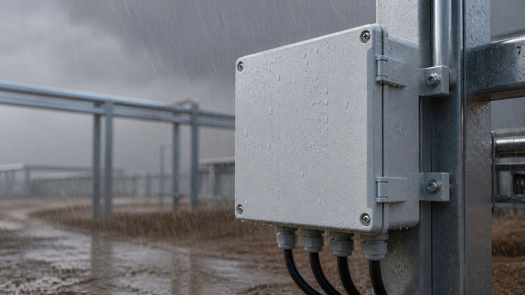
- Enclosure and environment. Envelope, IP class, ambient range and altitude. Standard operating range is -5 C to +40 C up to 2000 m.
- Interfaces. Communication protocol, remote signalling contacts, fire-alarm dual-disconnect, BMS integration.
- Certification. IEC 60947-6-1 as the baseline, plus whatever the destination market requires for import and inspection.
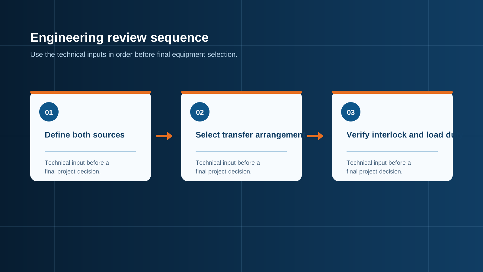
Technical diagram shown at a readable responsive scale.
This is general technical guidance, not a substitute for local electrical code, the applicable standard, product datasheets or a qualified engineer's design review. Confirm ratings and final configurations against the actual project.
Bring the project inputs to the first review.
NEUTRON can review the application context, electrical envelope, enclosure conditions and document requirements related to different types of changeover switches: the complete 2026 buyer's guide before quotation.
Discuss a technical requirementContinue learning
Explore related technical guidance in Power Distribution.
Converted from the approved Period 01 source article for Different Types of Changeover Switches: The Complete 2026 Buyer's Guide. Editorial instructions, duplicate anchor placeholders and embedded publishing directions were removed; the technical body is retained for educational use.