
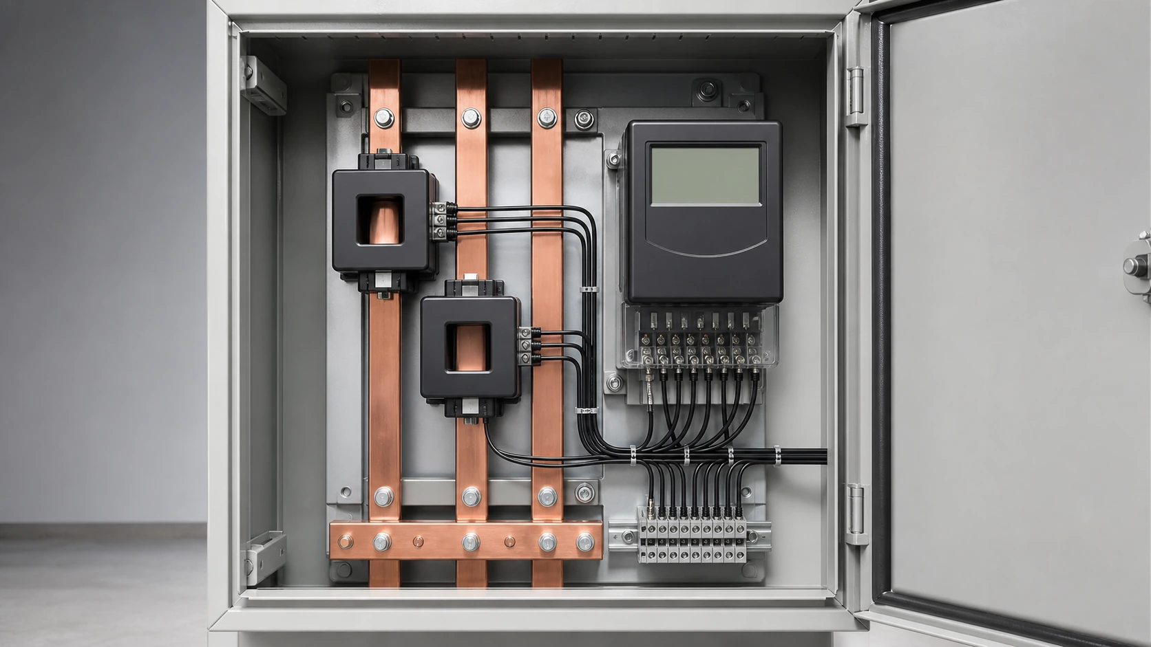
What a CT Accuracy Class Guarantees
IEC 61869-2 defines the metering accuracy class as maximum ratio error and phase displacement measured at specified percentages of rated primary current and across a defined burden window. Outside those test conditions, the class number does not provide the same guarantee.
A purchase specification should include the primary and secondary current, rated burden, frequency and instrument security factor. A 400/5 A CT and a 400/1 A CT can have very different cable burdens even when their accuracy class is identical.
Ratio Error and Phase Displacement
Ratio error is the percentage difference between the actual secondary current and the value predicted by the nameplate ratio. Magnetising current is a major contributor, especially at low primary current.
Phase displacement is the angle between primary and secondary current. It matters to energy measurement because energy calculations depend on the phase relationship between voltage and current, particularly on inductive or low-power-factor loads.
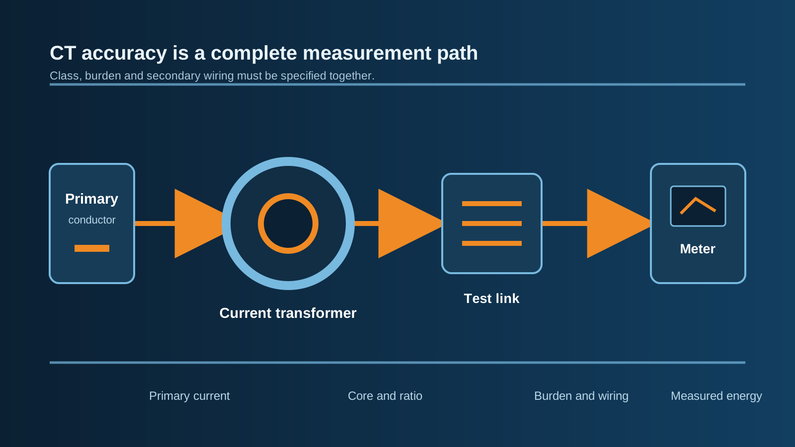
Technical diagram shown at a readable responsive scale.
Class 0.2 vs Class 0.2S
The S suffix indicates an extended-range metering class. Both class 0.2 and class 0.2S can hold the same stated error at full load; the difference is the lower end of the current range.
The supplied source states that class 0.2S is specified down to 1% of rated current, while standard class 0.2 is not guaranteed over the same low-load range. This matters on feeders that are heavily oversized relative to their overnight or light-load demand.
Accuracy Classes at a Glance
Use the table as a specification discussion starter; the applicable standard, test points and utility requirements control the final selection.
| Class | Typical use | Low-load behavior | Full-load error |
|---|---|---|---|
| 0.1 | Laboratory and test work | Very tight, defined by the standard | About +/-0.1% |
| 0.2 | High-grade panel metering | Not the same extended range as 0.2S | About +/-0.2% |
| 0.2S | Revenue and tariff metering | Extended low-current specification | About +/-0.2% |
| 0.5 / 0.5S | Industrial or sub-billing metering | S version improves low-load coverage | About +/-0.5% |
| 1 | Panel indication and load logging | Coarser indication duty | About +/-1% |
| 5P / 10P | Protection relays | Protection class, not revenue metering | Composite-error basis |
Burden, Wiring and Installation Factors
Everything on the secondary circuit contributes to burden: the meter, transducer, terminals, test links and both legs of the cable. Cable resistance can dominate the total, especially on a 5 A secondary over a long run.
- Avoid both over-burden and under-burden. Accuracy is verified in a defined burden window.
- Keep split-core mating faces clean and fully closed; an air gap can introduce a noticeable error step.
- Centre the primary conductor in the aperture and keep return conductors away from the window.
- Consider harmonics and DC offset from drives or rectifier loads when selecting the core.
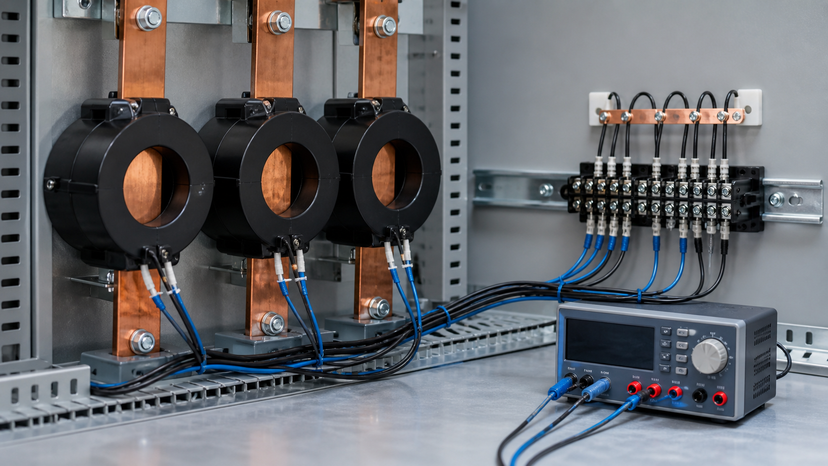
Integrating CTs into Metering and Switchgear Assemblies
The panel affects the accuracy budget. Provide a mechanically supported CT position, maintain the primary conductor position, route the secondary wiring neatly and include short-circuiting test terminals so a meter can be serviced safely.
The supplied source describes NEUTRON metering cabinets, incomer and feeder cabinets, GGD and GCS switchgear, XL-21 cabinets and package substations. The exact assembly current, voltage, short-circuit withstand, enclosure and documentation must be checked for the quoted build.
Mistakes That Cost Money on Site
- Using a protection core for a revenue meter or sharing one core between metering and protection.
- Selecting an oversized ratio that leaves normal operation at the least accurate part of the curve.
- Running a 5 A secondary over a long distance when a 1 A secondary would reduce cable burden.
- Leaving a CT secondary open-circuit during testing.
- Specifying the class without stating the burden, cable length and meter load.
A Copy-Ready CT Specification Pattern
A complete enquiry can state: window-type CT, ratio 800/5 A, accuracy class 0.2S to IEC 61869-2, rated burden 5 VA, FS5, 50/60 Hz, 0.72 kV insulation, aperture for the specified busbar and a routine test certificate with the required error points.
Send the single-line diagram, meter datasheet and secondary cable length with the enquiry so the burden window can be checked rather than assumed.
Accuracy figures are standard-dependent and must be verified against the current edition of IEC 61869-2, the utility metering code, the meter datasheet and the actual secondary circuit.
Frequently asked questions
What is the difference between CT class 0.2 and 0.2S?
Both are high-accuracy metering classes at their defined test points. Class 0.2S extends the specified low-current range, which is useful when a feeder spends significant time at light load.
Which CT class is used for revenue metering?
Many utility schemes use class 0.2S or 0.5S to IEC 61869-2, but the local network operator's metering code controls. Confirm whether the CT must be tighter than the meter.
Does phase displacement affect energy measurement?
Yes. Energy measurement depends on the phase relationship between voltage and current, so angular error can become material on inductive or low-power-factor loads.
What happens if the CT burden is too low?
The CT may operate below the burden window in which its accuracy was verified. Specify the burden with the meter, terminals and cable included in the calculation.
Can one CT core feed a meter and protection relay?
Normally no. Metering and protection cores have different duties and saturation behavior. Use separate cores or a purpose-designed dual-core transformer.
Start with the Meter and the Cable Run
Share the single-line diagram, target class, meter burden and secondary cable length so the CT and metering compartment can be reviewed together.
Request a quoteContinue learning
Explore related technical guidance in Power Distribution.

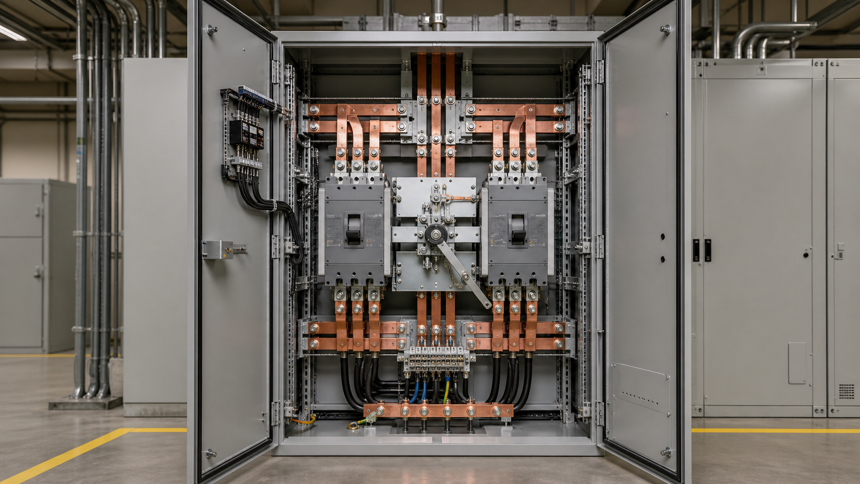
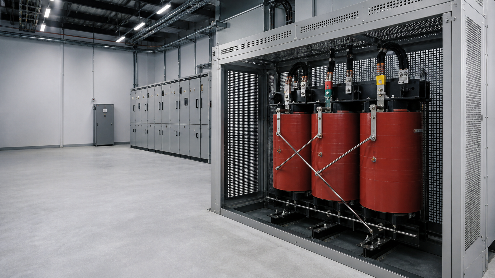
Adapted from the supplied DOCX. Numerical class limits and NEUTRON assembly capabilities should be confirmed against the current standard and quoted configuration.