
2. Transition Modes: Match Timing to Load Sensitivity
Transition mode is the first decision because it changes the price, the physical size and the electrical behaviour of the whole installation.
Table: ATS transition modes compared
**Delayed transition** deserves more attention than it usually receives. A motor that is disconnected keeps rotating and continues to generate a decaying back-EMF. Reconnecting it to a new supply out of phase produces a torque transient that can shear couplings and a current transient that trips upstream protection. A programmable dwell of 0.5 s to a few seconds eliminates the problem for a few percent on the purchase price.
**Closed transition** is attractive because a scheduled test transfer becomes invisible to the load, but it briefly parallels two supplies. That requires synchronisation checking, and in most jurisdictions it requires agreement from the network operator. Confirm both before specifying it.
1. What the ATS Has to Do
The job description is short: monitor two supplies, decide when the preferred one has failed, and connect the load to the alternative without ever paralleling the two unintentionally. Everything difficult about the specification follows from that last clause.
Transfer switching equipment is classified under **IEC 60947-6-1** as a **PC class** device, which can make and withstand short-circuit current but is not intended to break it, or a **CB class** device built from two interlocked circuit breakers, which can interrupt fault current. PC class units are compact, fast and mechanically simple, and dominate ratings up to about 1600 A. CB class units suit installations where the transfer device also has to provide overcurrent protection.
One further distinction matters commercially. A **transfer switch** is a component; an **ATS cabinet** is an assembly containing the switch, its controller, the incoming and outgoing terminations, auxiliary supplies and the enclosure — and it is the assembly that must be declared to **IEC 61439** for a project handover.
3. Electrical Ratings: Current, Voltage and Fault Withstand
**Current.** Size to the continuous load, not the peak on a nameplate. Transfer switches are rated for 100 % continuous duty in most catalogues, but the declared rating applies at a stated ambient temperature; a unit installed in an unventilated plant room at 45 °C may need derating. NEUTRON ATS cabinets cover 63 A to 3200 A in standard frames.
**Voltage and frequency.** Confirm 230/400 V, 415 V or 690 V and 50 Hz or 60 Hz against the destination market. Also confirm the rated insulation voltage and impulse withstand voltage, not just the operational figure.
**Withstand and closing ratings.** These are the specifications most often skipped, and the most consequential. **Icw**, the rated short-time withstand current, states the fault current the switch can carry for a stated time — typically 0.1 s to 1 s — while the upstream device clears. **Icm**, the rated short-circuit making capacity, states the fault it can safely close onto if it transfers into a downstream fault. Both must be coordinated with the prospective fault current at the point of installation and with the upstream protective device. A 400 A switch with 25 kA Icw installed on a busbar with 50 kA prospective fault current is a hazard, whatever its price advantage.
4. Pole Configuration: 3-Pole, 4-Pole and the Neutral
Pole count is not a preference. It follows from the earthing arrangement of the installation and from where the neutral-earth bond is made on each supply.
Get this wrong and the symptoms are intermittent and hard to diagnose: nuisance tripping of residual current devices, circulating currents in earth conductors, and touch voltages that appear only when the standby supply is running. Confirm the earthing arrangement of both supplies in writing before ordering.
- **3-pole:** switches the three phases and keeps the neutral solidly connected through the switch. Appropriate where both supplies share a single neutral-earth bond, typically a TN-S installation with one earthing point.
- **4-pole (switched neutral):** switches the neutral together with the phases. Required where the standby supply — usually a generator — has its own neutral-earth bond, because leaving both bonds connected creates a parallel earth path that carries neutral current through the earthing system and can cause residual current devices to misoperate.
- **4-pole with overlapping neutral:** the neutral pole makes before the phases break, so the load neutral is never left floating during transfer. The preferred arrangement where sensitive single-phase electronic equipment is on the load side.
- **2-pole:** single-phase installations, small telecom cabinets and residential backup.
5. Controllers, Timers and Communication
The controller is the part of the ATS that operators interact with, and the part most often over-specified. Start from the sequence of operation the site actually needs, then buy the controller that delivers it.
Buy communication only where a system exists to receive it. An unconnected protocol option is a line item, not a benefit. What no site should omit, however, is the exercise timer and the event log — they are the difference between a tested standby installation and an assumed one.
- **Sensing windows:** programmable under/over voltage, under/over frequency and phase loss detection on both supplies, with adjustable thresholds rather than fixed factory values.
- **Time delays:** a start delay to ride through momentary dips without a pointless transfer; a generator warm-up delay; a re-transfer delay so the load returns only after the utility has been stable for a set period; and a cool-down delay before the set shuts down under no load.
- **Generator control:** a volt-free start contact and a run-status input.
- **Test and exercise:** an on-load or off-load scheduled exercise routine, which is what keeps a standby installation credible.
- **Communication:** RS485 with Modbus RTU is the practical baseline for integration into building management. Confirm the register map before purchase.
- **Indication:** clear position indication, supply-available LEDs, an event log and volt-free auxiliary contacts for remote alarm.
6. Enclosure, Mounting and Environment
NEUTRON builds ATS cabinets in cold-rolled or galvanised steel, phosphated and electrostatically powder-coated in RAL 7035, wall-mounted or floor-standing depending on frame size, with copper busbar and defined terminal torque values. Ingress protection follows **IEC 60529** and the real mounting position:
Two environmental factors are routinely underestimated in tropical and coastal projects: condensation and corrosion. An anti-condensation heater with a hygrostat costs very little and prevents the insulation degradation that follows daily dew cycles inside an outdoor cabinet.
- **IP30 / IP40** — clean indoor switchroom or plant room.
- **IP54** — industrial indoor areas with dust, sheltered outdoor positions, generator housings.
- **IP65** — fully exposed outdoor sites, wind-blown sand, salt mist, washdown areas; stainless steel where coastal corrosion is severe.
- **Thermal design** — every switch dissipates heat at rated current. Confirm the ambient temperature assumption, provide ventilation or forced cooling where required, and derate where it is not.
- **Access and maintenance** — front access clearance for terminal inspection, torque checks and thermographic survey; lockable door; clear phase and terminal marking.
7. Standards, Testing and Procurement Checklist
A standby installation is only as good as its last successful transfer. Specify the exercise routine at purchase, run it monthly, and log the result — that discipline finds more problems than any amount of additional hardware.
- Switch declared to **IEC 60947-6-1**; assembly declared to **IEC 61439-1/-2**; ingress protection to **IEC 60529**.
- Utilisation category and class (PC or CB) stated on the offer, with Icw and Icm figures, not just a current rating.
- Ambient temperature basis of the current rating stated, and derating curves supplied.
- Pole configuration confirmed against the earthing arrangement of both supplies.
- Transition mode confirmed against load type; delayed transition where motor load is significant.
- Controller sequence of operation agreed in writing, including all time delays and the exercise routine.
- Routine test report supplied: dielectric test, insulation resistance, earth continuity, mechanical and electrical operation, controller function.
- **CE** and **CB** documentation, **ISO 9001** manufacturer, and clear nameplate data for the destination market.
- Commissioning plan that transfers and re-transfers under real load, with timings recorded in the handover file.
- Spares policy: control fuses, auxiliary contacts and the controller itself for critical installations.
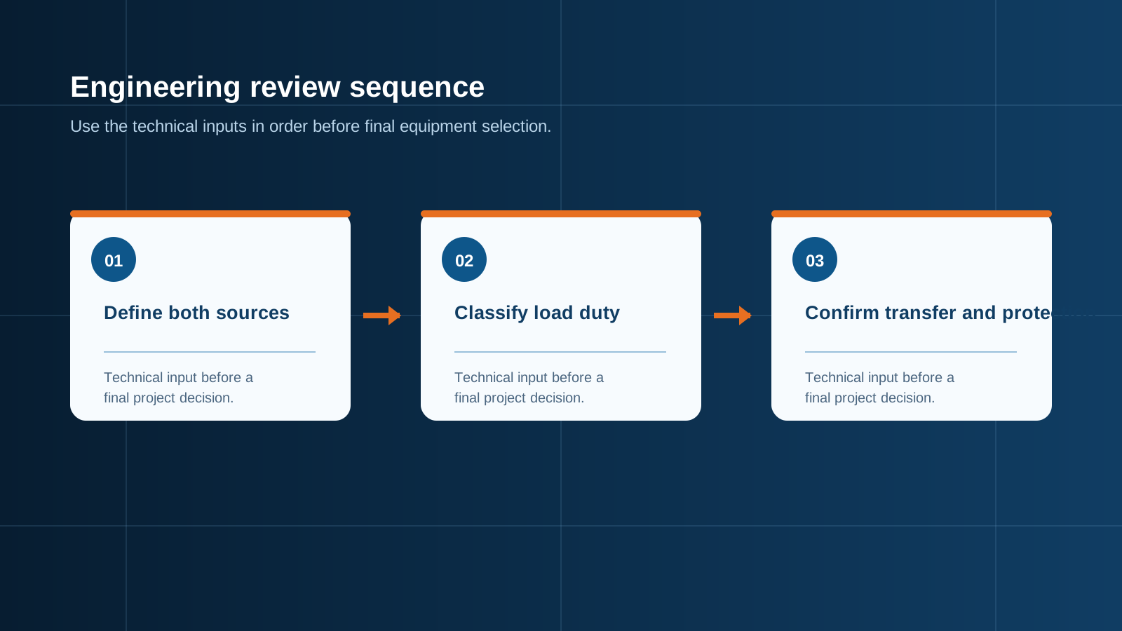
Technical diagram shown at a readable responsive scale.
Media & Assets
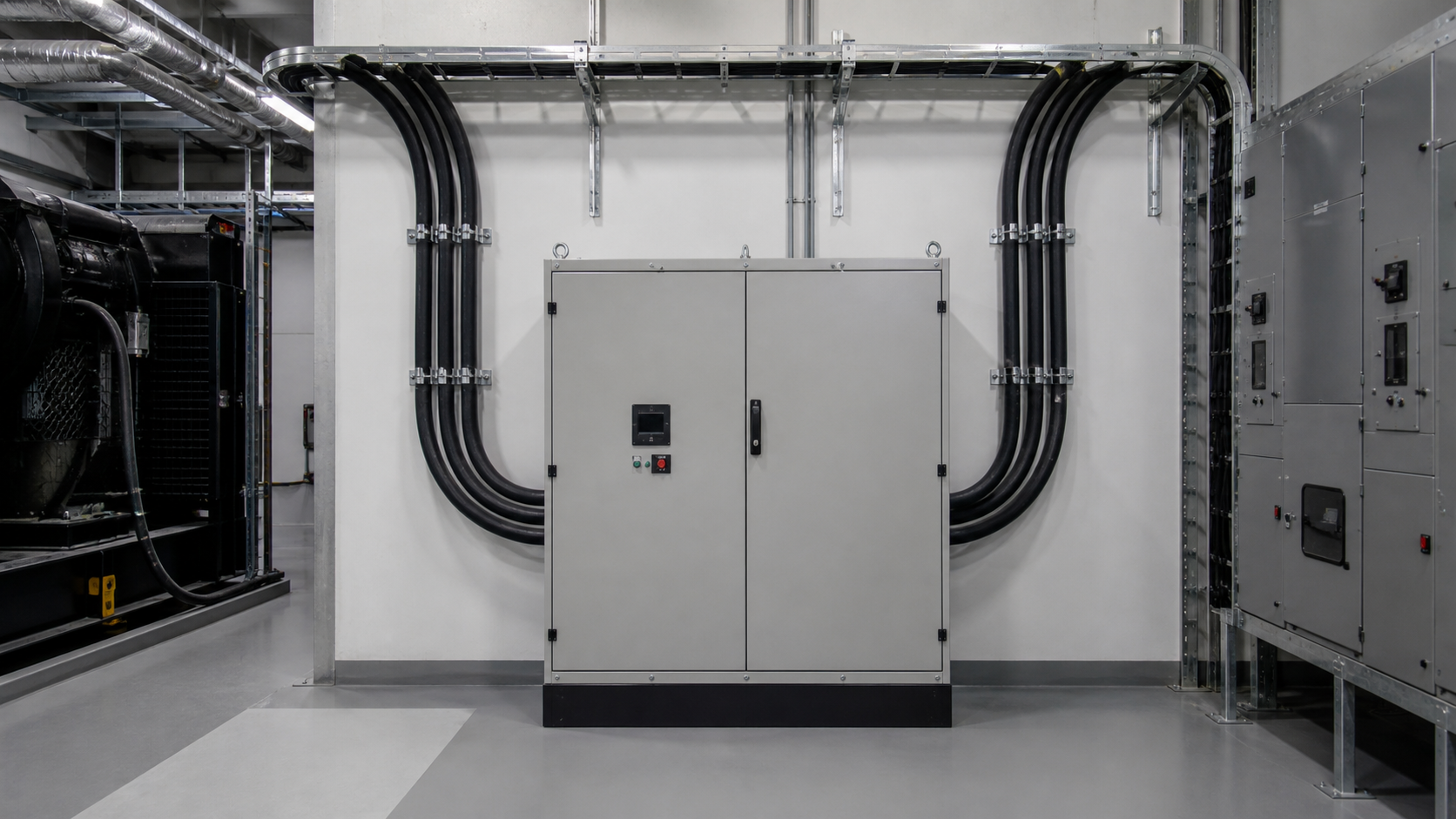
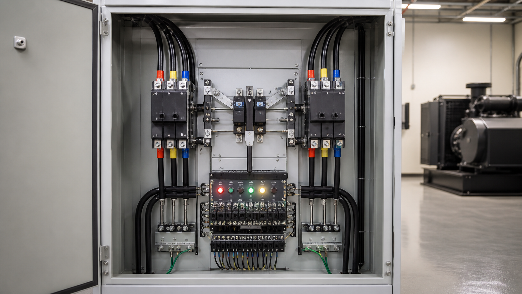
Subject: NEUTRON floor-standing ATS cabinet in an industrial switchroom, door open, showing a four-pole automatic transfer switch and controller
Style: clean industrial B2B product photography
Details: RAL 7035 powder-coated steel cabinet, copper busbar, four-pole transfer switch, digital controller with LCD, labelled utility and generator cable entries, cable gland plate
Background: clean industrial switchroom with adjacent low-voltage panels
Lighting: soft even indoor lighting
Aspect ratio: 16:9 (hero)
No text, no logos unless specified.
Subject: timing diagram comparing open, delayed and closed transition transfer
Style: technical line diagram, flat vector, three stacked timelines
Details: each timeline shows utility supply, standby supply and load voltage against time, with the interruption window or overlap window highlighted and labelled
Background: plain white
- Hero image: 16:9 at the top of the article, above the Key takeaway block.
- Inline image 1 (16:9 diagram): directly under the Section 2 transition mode table.
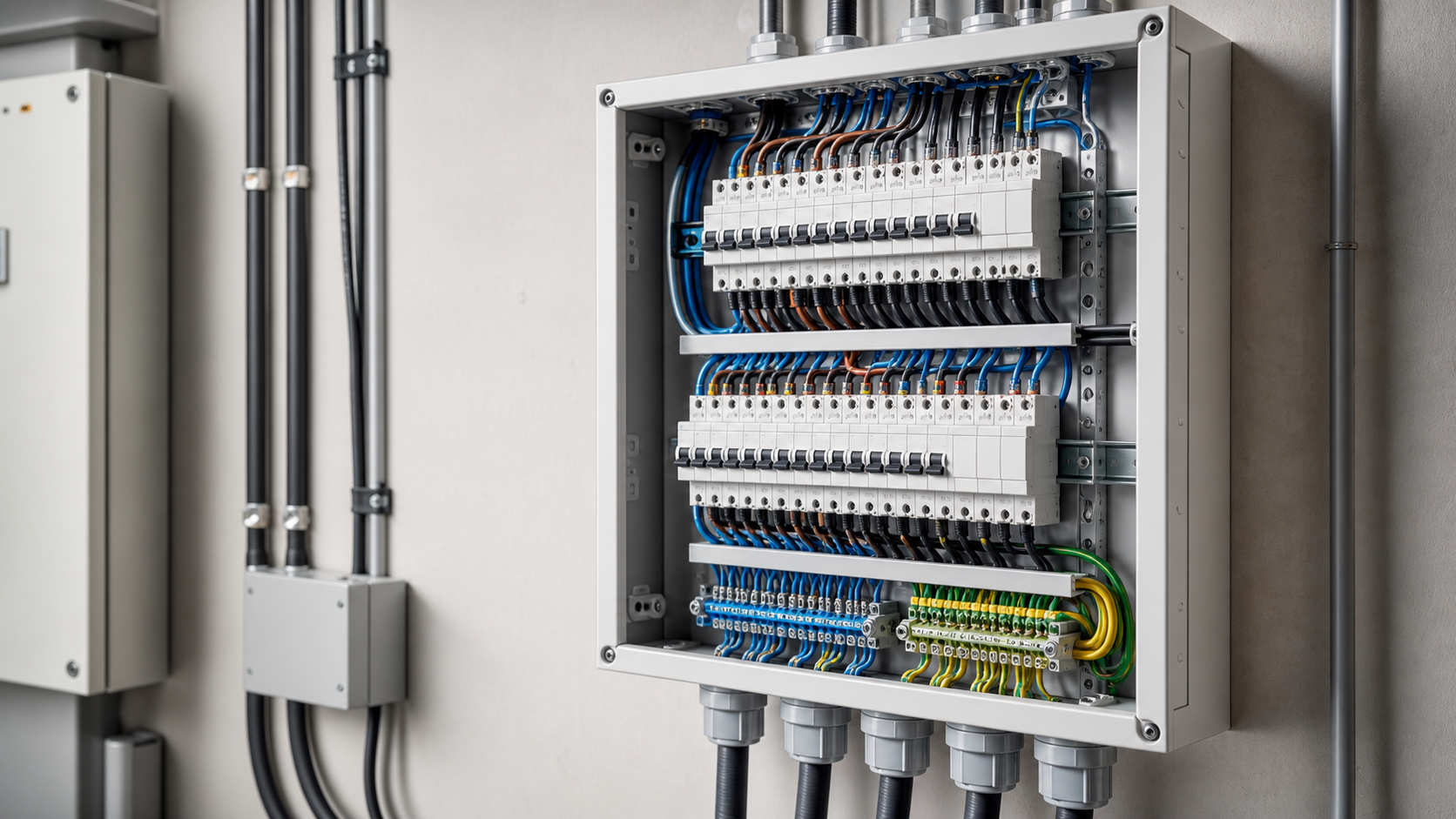
- Inline image 2 (4:5): inside Section 4, illustrating 3-pole vs 4-pole neutral handling.
- Inline image 3 (1:1): inside Section 5, controller close-up.
- Set explicit dimensions and loading="lazy" on all inline images.
This is general technical guidance, not a substitute for local electrical code, the applicable standard, product datasheets or a qualified engineer's design review. Confirm ratings and final configurations against the actual project.
Bring the project inputs to the first review.
NEUTRON can review the application context, electrical envelope, enclosure conditions and document requirements related to key features to consider when selecting an ats for backup power before quotation.
Discuss a technical requirementContinue learning
Explore related technical guidance in Power Distribution.
Converted from the approved Period 01 source article for Key Features to Consider When Selecting an ATS for Backup Power. Editorial instructions, duplicate anchor placeholders and embedded publishing directions were removed; the technical body is retained for educational use.