
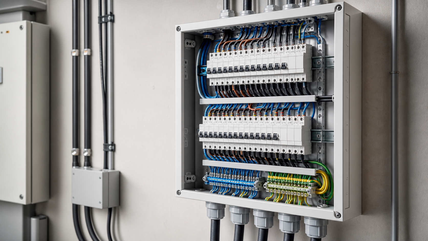
1. Anatomy of a distribution box
Every distribution board, from a six-way consumer unit to an XL-21 power cabinet, is built from the same functional blocks. Wiring logic follows from them.
The main switch and the outgoing devices are wired in series; the outgoing devices are wired in parallel with each other. That one sentence explains why a busbar comb works and why every outgoing way must be individually protected.
- Incoming terminals — where the supply cable lands, sized for the full board rating.
- Main switch or main breaker — isolates the whole board. A main switch isolates only; a main breaker also protects the board and provides backup to the outgoing ways.
- Line busbar or comb — distributes the line conductor to each outgoing device without individual looping.
- Outgoing protective devices — MCBs, RCBOs, RCCBs, MCCBs, arc fault detection devices.
- Neutral bar — a common terminal block for outgoing neutrals, usually blue.
- Earth bar — protective conductor terminals, yellow-green, bonded to the enclosure.
- Enclosure and DIN rail — mechanical support and the protection class boundary.
2. Earthing arrangement decides the wiring
Before any device is fitted, the earthing arrangement must be known. It changes how the neutral and earth bars are treated.
The practical rule for panel builders: downstream of the point of separation, the neutral bar and earth bar are never bonded together. Linking them defeats residual current protection entirely and creates parallel neutral paths through the earthing system.
| Arrangement | Neutral and earth relationship at the board | Practical wiring consequence |
|---|---|---|
| TN-S | Separate neutral and protective conductors throughout | Independent neutral bar and earth bar, never linked at the board |
| TN-C-S (PME) | Combined upstream, separated at the origin | Neutral and earth bars separate downstream of the separation point |
| TT | Earth via a local electrode, independent of the supply neutral | Residual current protection is mandatory for fault protection, not just additional protection |
| IT | No direct earth connection of the supply | Insulation monitoring required; residual current strategy differs |
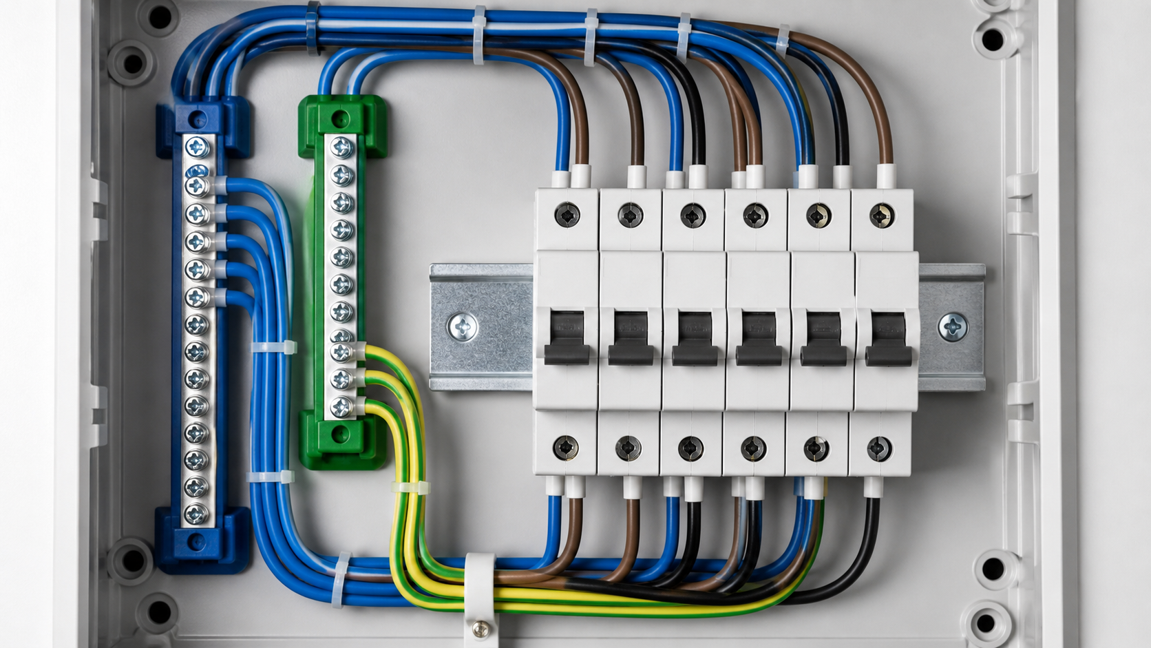
3. Single-phase configurations: 1P and 1P+N
1P MCB with common neutral bar
The most common arrangement. The line conductor enters via the busbar comb to each single-pole MCB; the outgoing line leaves from the device terminal; the circuit neutral returns directly to the shared neutral bar. Compact and inexpensive. The limitation is that isolation is single-pole — the neutral remains connected when the breaker is off, which some national regulations restrict for certain circuits.
1P+N MCB
Switches line and neutral together, giving true double-pole isolation of the circuit. It occupies more module width and requires the circuit neutral to be landed on the device rather than the neutral bar. Preferred where full isolation is required, for example on socket circuits in some jurisdictions or where a circuit may be worked on while the board stays live.
Ordering the ways
Arrange outgoing ways by function and rating rather than at random: largest fixed loads nearest the incomer, then socket circuits, then lighting. It shortens internal conductors, reduces heating in the busbar and makes the finished board legible to whoever maintains it in ten years.
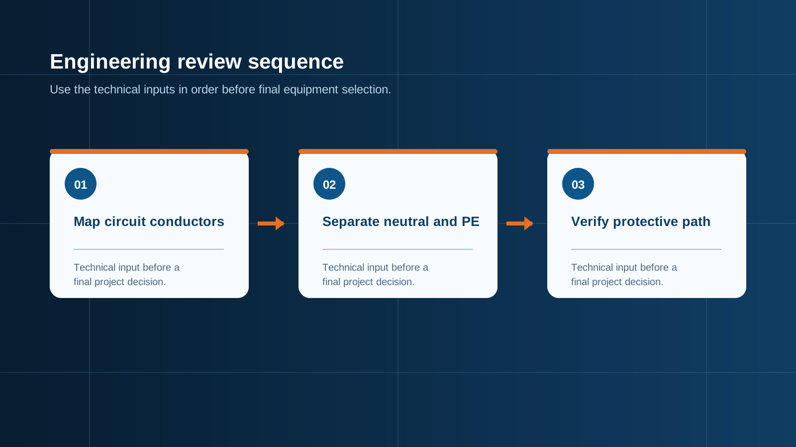
Technical diagram shown at a readable responsive scale.
4. Three-phase configurations: 3P and 4P
A three-phase board distributes L1, L2 and L3 across a three-phase comb, with the neutral on a separate bar. Outgoing devices take one, two or three phases depending on the load.
For a three-phase motor, the three-pole device switches all phases simultaneously — essential, because losing one phase to a motor causes single-phasing and rapid winding damage. For a sub-board feed, a four-pole device is generally correct so that the downstream board can be fully isolated.
5. Wiring MCBs, RCCBs and RCBOs correctly
Residual current devices are where wiring goes wrong most often, because they impose neutral rules that ordinary MCBs do not.
MCB — IEC 60898-1
Overcurrent protection only. Line in from the comb, line out to the circuit, neutral direct to the neutral bar. Curve selection matters: Type B for resistive and general loads, Type C for moderate inrush such as fluorescent banks and small motors, Type D for high inrush such as transformers and welding equipment.
RCCB — IEC 61008-1
Residual current detection only, with no overcurrent protection of its own. It must always sit downstream of an overcurrent device rated at or below the RCCB's rated current. The critical wiring rule: every circuit protected by an RCCB must return its neutral to that RCCB's own neutral terminal or dedicated neutral bar — never to the general neutral bar. A single misrouted neutral produces an imbalance the device reads as a fault, and the RCCB trips as soon as load is applied.
RCBO — IEC 61009-1
Combines residual current detection and overcurrent protection in one device. Line in from the comb, line out to the circuit, and the circuit neutral lands on the RCBO's neutral terminal. The device's own neutral pigtail then goes to the neutral bar. Busbar combs must not bridge across the neutral poles of RCBOs — use a comb designed for RCBO line poles only, or individual line conductors.
Residual current sensitivity follows the duty: 30 mA for additional protection of socket circuits and personnel, 100 mA or 300 mA for fire protection and upstream duty. Type matters too — Type AC for pure alternating residual currents, Type A where pulsating DC components exist from electronic loads, and Type B for variable-speed drives and PV inverters producing smooth DC residual current.
6. Phase balancing in multi-way panels
Balancing is a wiring decision made at build time, not a commissioning afterthought.
The consequences of ignoring this are concrete. Unbalanced loading produces neutral current that can approach or exceed phase current where harmonic-rich electronic loads dominate, causing neutral conductor overheating. It also creates voltage imbalance across phases, which increases motor losses and shortens winding life. On a three-phase four-wire board serving IT or LED lighting loads, size the neutral for the full phase current — the traditional assumption that the neutral carries less is no longer safe.
- List every outgoing circuit with its design current, not its breaker rating. A 20 A breaker on a 4 A lighting circuit contributes 4 A to the balance.
- Apply diversity appropriate to the load type before allocating.
- Distribute circuits across L1, L2 and L3 so that calculated phase currents sit within roughly 10 % of each other.
- Group by simultaneity, not just by size. Three large loads that never run together can share a phase; three that always run together should not.
- Record the allocation on the schedule inside the door, so future additions preserve the balance.
7. Conductor sizing, terminals and torque
Busbar comb rules deserve their own note. Combs are rated — a comb rated 63 A cannot feed a group of devices drawing more. Cut ends must be insulated with the supplied end caps, unused teeth must not remain exposed, and the comb must not bridge devices fed from different phases or across residual current device boundaries.
- Size internal conductors for the device rating and the enclosure ambient, applying grouping and temperature derating. Internal panel temperatures run well above room temperature.
- Match conductor colours to the applicable convention and keep them consistent — brown, black, grey for lines, blue for neutral, yellow-green for protective conductors under the common IEC convention.
- Use ferrules on stranded conductors in screw terminals. Bare stranded conductors spread under pressure and loosen.
- Never land two conductors in a terminal rated for one. Use a two-conductor terminal or a distribution block.
- Torque every terminal to the manufacturer's figure with a calibrated torque screwdriver, and mark checked terminals. Loose connections are the leading cause of distribution board thermal failure.
- Re-check torque after the first thermal cycles on high-current terminations.
- Leave the schematic inside the door and label every way clearly.
8. Commissioning tests before energising
- Visual inspection — correct devices fitted, labelling complete, no exposed comb teeth, all covers and blanking plates in place.
- Continuity of protective conductors — every earth terminal to the main earth bar, target 0.1 Ω or less on assembly earth circuits.
- Insulation resistance — line and neutral to earth with the board isolated and sensitive electronics disconnected.
- Polarity verification — every outgoing way confirmed line, neutral and earth in the correct terminals.
- Residual current device testing — trip at rated residual current within 300 ms, and at five times rated residual current within 40 ms for general-type devices. Selective S-type devices have their own longer time window.
- Phase rotation check on three-phase outgoing ways serving motors.
- Load test and thermal check — energise progressively and check terminations with a thermal camera under load.
- Record everything on a test certificate issued with the board.
9. Common wiring errors
- Neutral of an RCD-protected circuit landed on the general neutral bar. Immediate nuisance tripping under load.
- Busbar comb bridged across RCBO neutral poles. Short circuit between neutrals of different circuits.
- Neutral and earth bars linked downstream of the separation point. Destroys residual current protection.
- Shared neutrals between circuits on different phases. Overloads the shared conductor and defeats isolation.
- All heavy loads allocated to one phase. Overheating, voltage imbalance and wasted capacity.
- Wrong MCB curve. Type B on a motor circuit trips on inrush; Type D on a lighting circuit will not clear a fault fast enough.
- Untorqued or over-torqued terminals. Loose joints overheat; over-torqued ones crush conductors.
- No circuit schedule. Guarantees the next person gets it wrong.
10. NEUTRON distribution boards and power cabinets
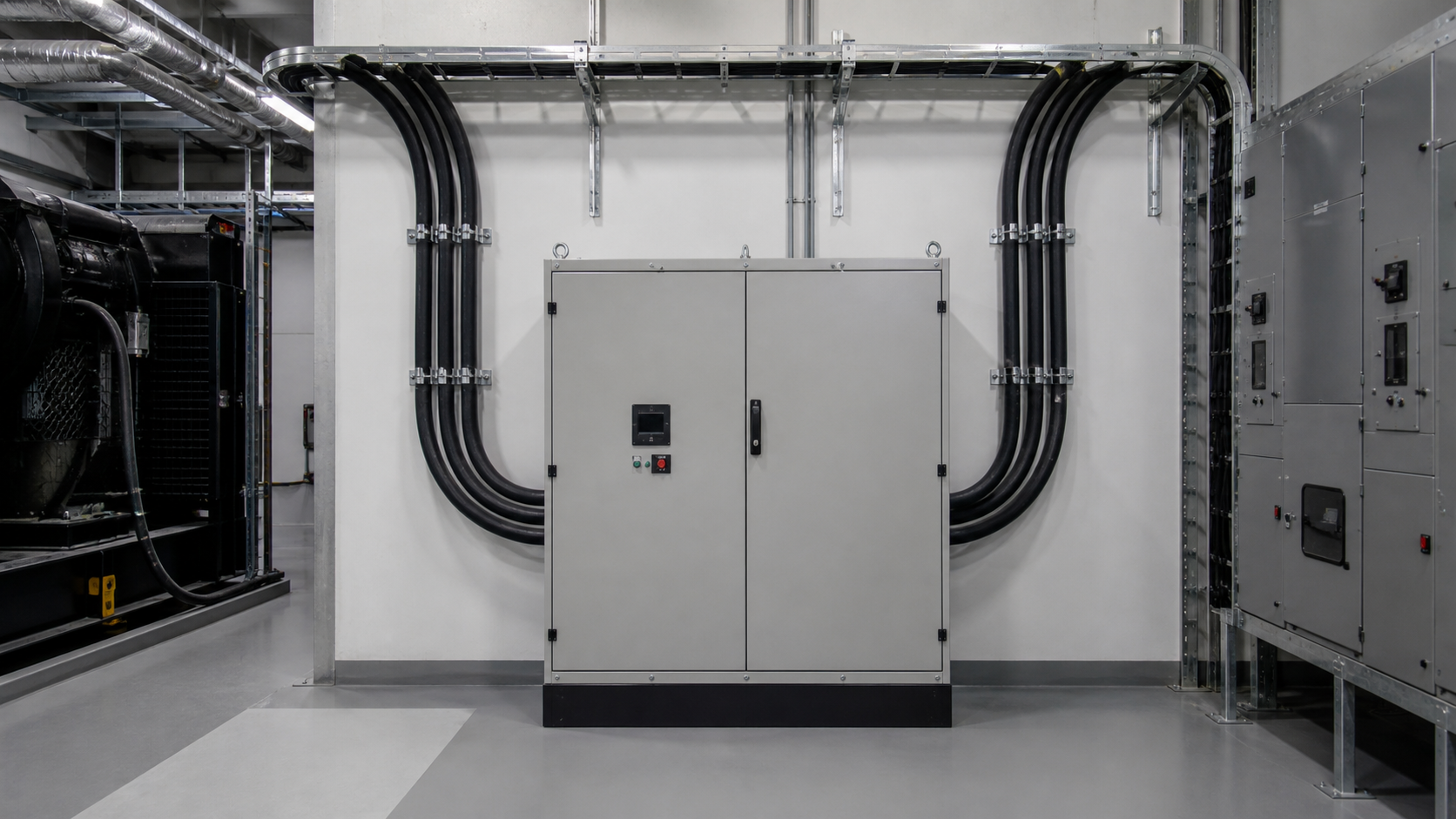
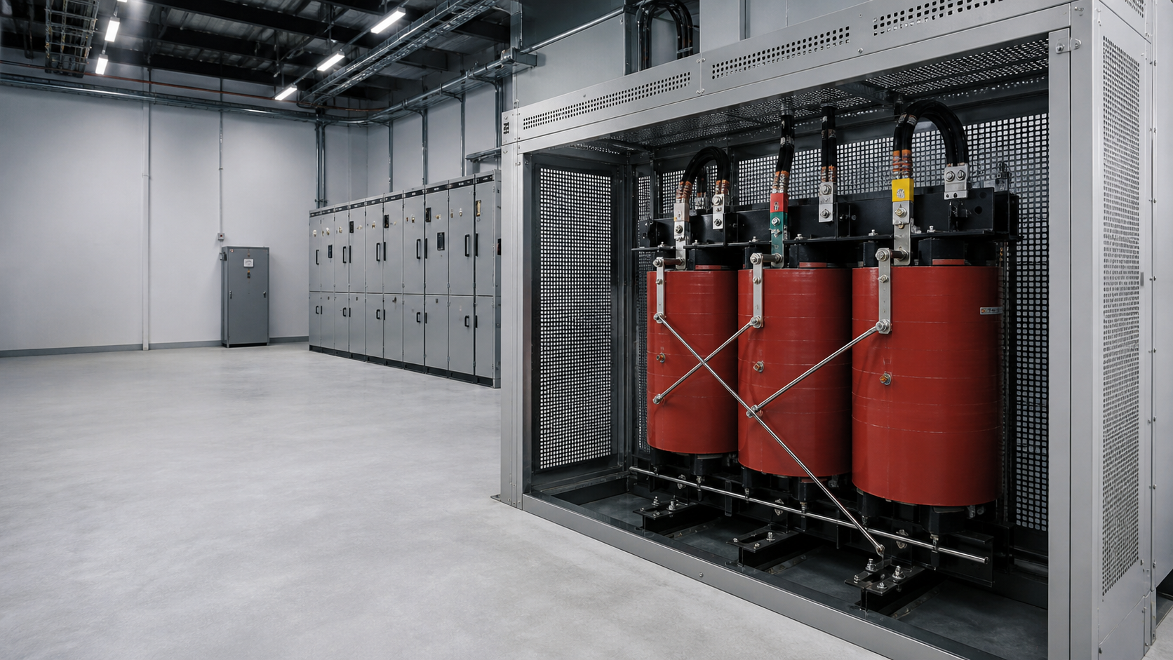
NEUTRON builds distribution assemblies from wall-mounted boards up to floor-standing switchgear lineups, wired and tested to project drawings.
Boards ship with the wiring diagram inside the door, a labelled circuit schedule, and a routine test record. Custom way counts, terminal arrangements, cable entry positions and label languages are configured per project.
Safety and limitations: distribution board work must be carried out by qualified electrical personnel following safe isolation procedures. National wiring regulations govern device selection, residual current requirements, conductor colours and isolation rules, and they differ significantly between markets. Confirm the applicable local requirements before finalising any board design.
Next step
Specifying a distribution board or power cabinet? Send your circuit schedule, fault level, protection class and destination market. NEUTRON engineering will return a wired and tested assembly specification with drawings.
Browse distribution cabinets and switchgear → https://neutronele.com/products/
This is general technical guidance, not a substitute for local electrical code, the applicable standard, product datasheets or a qualified engineer's design review. Confirm ratings and final configurations against the actual project.
Bring the project inputs to the first review.
NEUTRON can review the application context, electrical envelope, enclosure conditions and document requirements related to circuit breaker wiring configurations in distribution boxes before quotation.
Discuss a technical requirementContinue learning
Explore related technical guidance in Power Distribution.
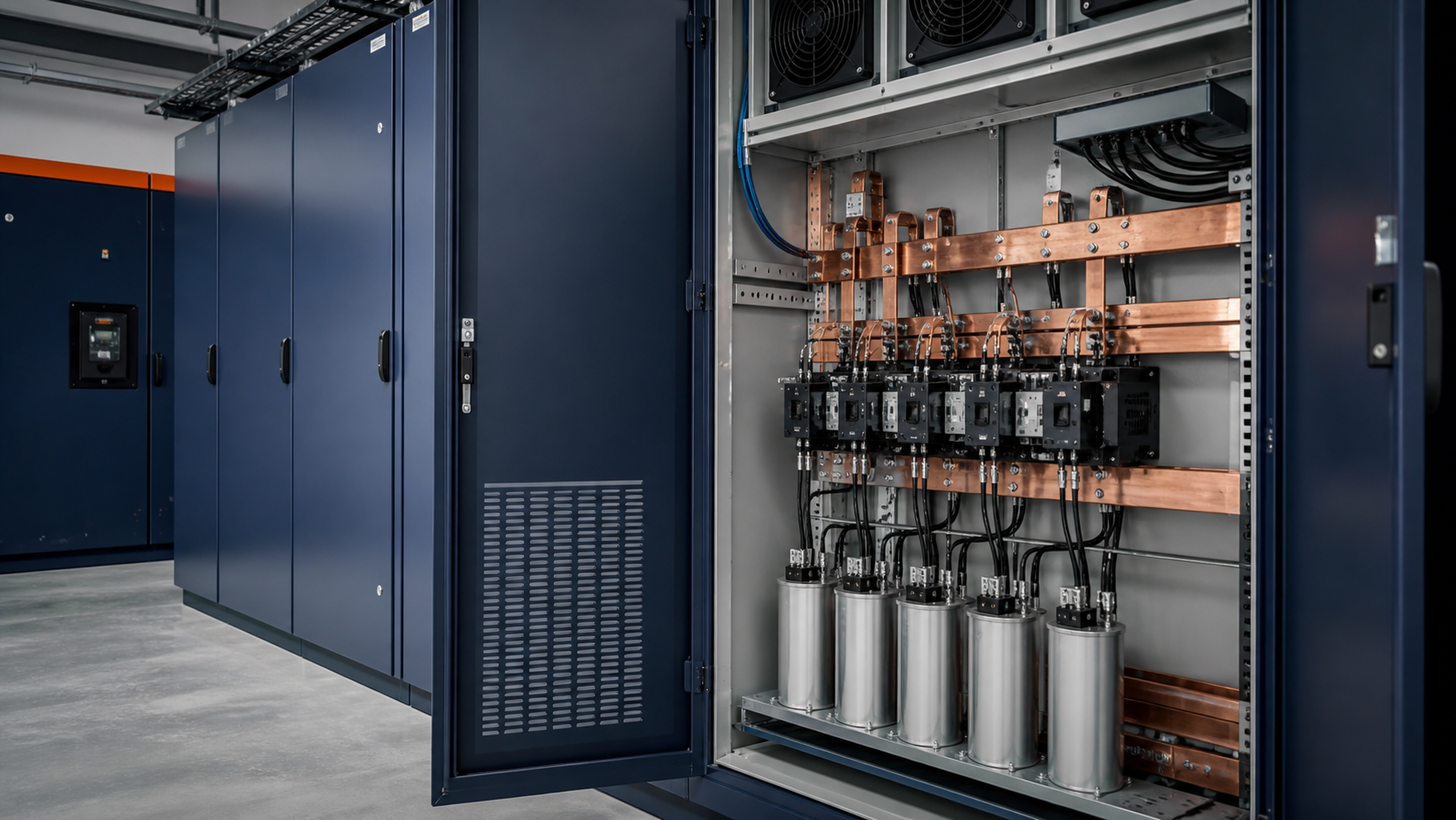
Converted from the approved Period 01 source article for Circuit Breaker Wiring Configurations in Distribution Boxes. Editorial instructions, duplicate anchor placeholders and embedded publishing directions were removed; the technical body is retained for educational use.